Insulated Investment Casting Mold and Method of Making

a technology of investment casting and molds, which is applied in the field of a method of making investment casting shell molds, can solve the problems of affecting the quality of finished metal products

Inactive Publication Date: 2011-05-19
CERADYNE
View PDF15 Cites 27 Cited by
  • Summary
  • Abstract
  • Description
  • Claims
  • Application Information

AI Technical Summary

Benefits of technology

[0010]The present invention provides an investment casting shell mold and method of making. The insulated investment casting shell mold is an improved alternative to the prior art means of controlling or slowing the cooling of a filled investment casting shell mold in order to prevent finished metal defects such as no-fill and undesired grain structure in the finished article. Such defects can be prevalent in parts with thin cross-section areas where rapid cooling of the molten metal is more likely to occur. Rapid cooling of the molten metal within the shell mold can cause a loss of molten metal fluidity resulting in no-fill defects, and a lack of time at a given temperature resulting in undesirable metallurgical properties in the finished metal article. The method of making the insulated investment casting shell mold is applicable to the conventional manufacture of a refractory mold wherein a multi-layered shell is formed by successively coating and hardening slurries comprising a binder and a refractory material on a pattern and thereafter eliminating the pattern. When an investment casting shell mold is manufactured in accordance with the invention, its thermal insulating means is incorporated in situ within at least a portion of the wall of the shell itself. In accordance with the method, even distributions of void or gaseous spaces are embedded in at least a portion of at least one of the slurry coats subsequent to a prime coat.

Problems solved by technology

Such defects can be prevalent in parts with thin cross-section areas where rapid cooling of the molten metal is more likely to occur.
Rapid cooling of the molten metal within the shell mold can cause a loss of molten metal fluidity resulting in no-fill defects, and a lack of time at a given temperature resulting in undesirable metallurgical properties in the finished metal article.

Method used


Image

  • Insulated Investment Casting Mold and Method of Making
  • Insulated Investment Casting Mold and Method of Making

Examples


examples

[0026]In order that the present invention may be more fully understood, examples will now be presented describing alternative process steps that have been taken to form the insulated investment casting shell mold and characteristics of the resulting shell molds. It is to be understood that these examples are not to limit the present invention but are given to describe several embodiments of the process of making and the characteristics of embodiments of the shell mold.

examples 1-20

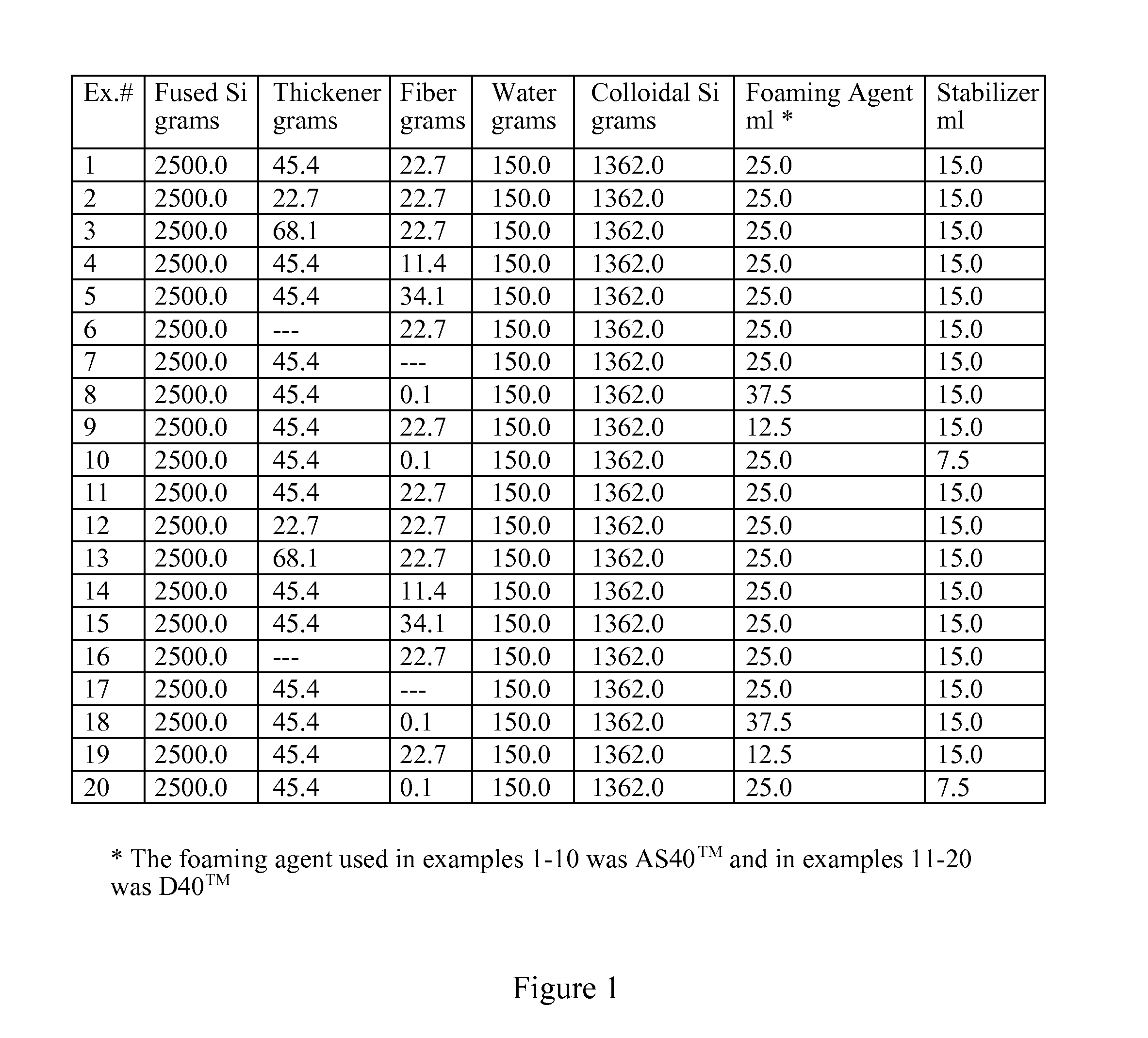
[0027]Insulated investment casting foam slurries were individually prepared with the constituents as shown in FIG. 1 by the following steps:

[0028]1362 grams of colloidal silica were added to a mixing vessel.

[0029]150 ml of water was added to the mixing vessel.

[0030]The mixing vessel was placed in a high shear mixer having a 3 inch high shear mixing propeller.

[0031]The propeller was lowered into the container to within ½ inch of the bottom of the mixing vessel.

[0032]2500 grams of fused silica were added to a dry container.

[0033]An amount of bentonite clay thickener was optionally added to the dry container of the example as indicated in the table of FIG. 1.

[0034]An amount of E385F™ fibers were optionally added to the dry container of the example as indicated in the table of FIG. 1.

[0035]The dry materials in the dry container were poured on top of the liquid materials in the mixing vessel.

[0036]The high shear mixer was turned on to provide approximately 500 rpm to the high shear mixin...

example 21

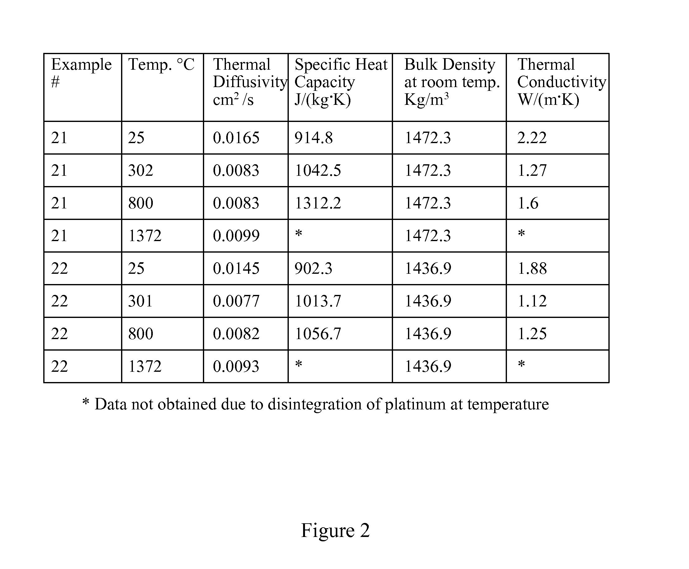
[0046]A flat shell section was produced by first dipping a wax plate pattern into a slurry having 3711 g of fused silica, 175 g water, 1362 g colloidal silica, and 140 g Minco HP latex. followed by application of Minco 30×50 stucco. The shell mold was then dipped into the slurry and stucco was applied a plurality of times resulting in a coating of approximately 0.5″ in thickness on the wax pattern. The shell mold's edges were ground allowing removal of the shell in plate form from the wax pattern. Thermal diffusivity, specific heat capacity, bulk density, and thermal conductivity were measured at varying temperatures, the results of which appear in the table of FIG. 2. Thermal diffusivity and specific heat capacity tests were performed according to the specifications of ASTM E1461 test method.


PUM

PropertyMeasurementUnit
temperatureaaaaaaaaaa
lengthaaaaaaaaaa
refractoryaaaaaaaaaa

Abstract

An insulated investment casting shell mold is made by first mixing at least one refractory material with a slurry vehicle forming a prime coat slurry, and optionally mixing at least one refractory material with a slurry vehicle forming a backup slurry. The prime slurry is coated onto a fugitive pattern and optionally dried and/or stuccoed wherein the stucco has at least one refractory material. Optionally, at least one coat of the backup slurry is applied to the prime coated fugitive pattern and optionally dried and/or stuccoed after each coat of the backup slurry. The backup and stucco may be applied a plurality of times to obtain a desired shell wall thickness. An insulating slurry is formed by introducing gas into a slurry vehicle having at least one refractory material and containing a stabilizer and a foaming agent wherein gaseous bubbles become entrained therein forming an insulating slurry having closed porosity therein. The insulating slurry is coated onto at least one portion of the pattern after the prime coat and preferably at least a portion of the outermost layer of a backup coated pattern has the insulating slurry thereon.

Description

CROSS-REFERENCE TO RELATED APPLICATIONS[0001]This continuation-in-part application under 35 USC §120 claims priority to, and benefit from, U.S. application Ser. No. 11 / 668,709 filed on Jan. 30, 2007, entitled “Insulated Casting Mold and Method of Making” which is currently pending.FIELD OF INVENTION[0002]This invention relates generally to casting and more specifically to an investment casting shell mold and a method of making investment casting shell molds.BACKGROUND OF THE INVENTION[0003]A substantial number of metal castings are created by pouring molten metal into a sand or investment casting shell mold. Sand casting is typically performed when the article need not have intricate detail or is later machined and the mold is typically made of sand held together with various binders. In investment casting, the mold is typically made of refractory materials bound together with various binders. Investment casting shell molds are used typically when a precision cast article is desired...

Claims


Application Information

Patent Timeline
Patent Type & Authority Applications(United States)
IPC IPC(8): B22C9/04B22C9/12B22C9/18C04B35/66
CPCB22C7/02B22C9/04C04B2235/9607C04B2235/77C04B2235/6027C04B35/14C04B35/6263C04B35/62665C04B35/6316C04B38/0615C04B2111/00922C04B2235/349C04B2235/5212C04B38/067C04B38/10
Inventor SCOTT, DAVID H.
Owner CERADYNE
Why Eureka
Try Eureka