Fluid coking unit stripper

a technology of coking unit and stripper, which is applied in the direction of oven details, thermal non-catalytic cracking, and incrustation prevention/removal of oven, etc., can solve the problems of uneven or too heavy coating of coke particles, insufficient fluidization of heavier coke particles, and the accumulation of deposits on strippers can become so severe, so as to achieve good interstitial performance

Inactive Publication Date: 2011-05-19
EXXON RES & ENG CO
View PDF4 Cites 14 Cited by
  • Summary
  • Abstract
  • Description
  • Claims
  • Application Information

AI Technical Summary

Benefits of technology

[0010]In spite of these efforts, an improved stripper shed configuration would be desirable, combining the att

Problems solved by technology

During the contacting of the feed with the fluidized bed, some coke particles may become unevenly or too heavily coated with feed and during collision with other coke particles may stick together.
These heavier coke particles may not be efficiently fluidized by the steam injected into the bottom of stripper section so that they subsequently pass downwards from the reactor section into the stripper section where they may adhere to and build up on the sheds in the stripper section, mainly on the uppermost rows of sheds.
Accumulation of deposits on the stripper sheds can become so severe due to growth of the deposits into the open area between the sheds on the row above as to restrict fluidization of the coke in the reactor section and eventually shut the unit down.
As this material progresses through the stripper, additional cracking reactions occur.
With basic fluid cokers, unlike Flexicokers, this phenomenon is not greatly disadvantageous as the quantities are small but in the case of Flexicokers, this material is sent to the heater, where it is exposed to a high temperature, oxy

Method used


Image

  • Fluid coking unit stripper
  • Fluid coking unit stripper
  • Fluid coking unit stripper

Examples


Embodiment Construction

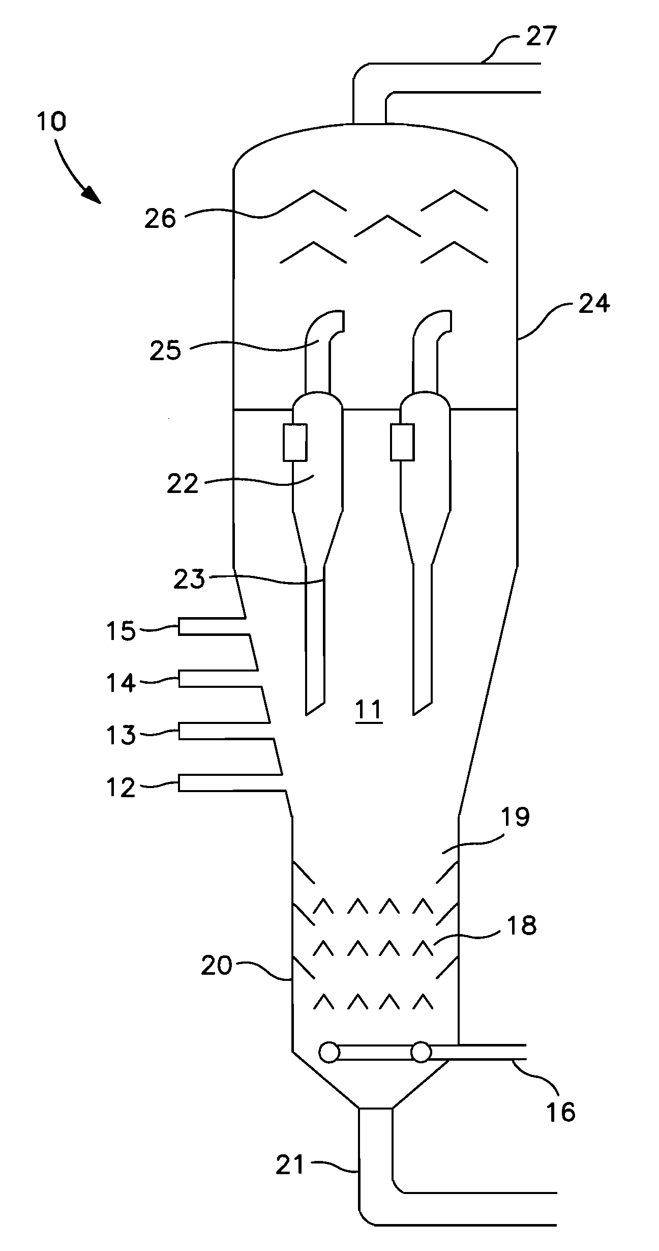
[0022]In FIG. 1 which is a highly simplified diagram of the reactor of a fluid coking unit, the reactor 10 contains a fluidized bed in coking zone 11 of heated seed coke particles into which the feedstock, heated to a temperature sufficient to initiate the coking (thermal cracking) reactions and deposit a fresh coke layer on the hot fluidized coke particles circulating in the bed. The feed is injected through a ring of feed injection ports 12, 13, 14, 15 which are positioned so that the feed with the atomizing steam enters directly into the fluidized bed 11 of hot coke particles. A fluidizing gas, usually steam, is admitted at the base of coker reactor 10, through conduit 16, into stripping zone 20 of the coking reactor in an amount sufficient to obtain a superficial fluidizing velocity in the coking zone, typically in the range of about 0.15 to 1.5 m / sec (about 0.5 to 5 ft / sec). The coking zone is typically maintained at temperatures in the range of 450 to 650° C. (about 840 to 120...


PUM


Abstract

An improved, fouling-resistant configuration for the stripper sheds of fluid coking units comprises an inverted, open-bottomed channel with apertures spaced along the length of the channel and spaced from the apex of the channel. Preferably, the channels are of an inverted-V configuration with a downwardly extending lip provided on each side of the channel, extending from the bottom edge of each side of the channel. The stripper sheds may be positioned parallel to one another in the stripper section of the reactor vessel or, alternatively, the sheds in different tiers in the stripper section may be disposed so that the longitudinal axes of the sheds are rotated angularly relative to the sheds in other rows.

Description

CROSS REFERENCE TO RELATED APPLICATIONS[0001]This application relates and claims priority to U.S. Provisional Patent Application Ser. No. 61 / 300,372, filed on Feb. 1, 2010 and U.S. Provisional Patent Application Ser. No. 61 / 280,625, filed on Nov. 6, 2009.FIELD OF THE INVENTION[0002]This invention relates to an improved stripper section for mitigating fouling and hydrocarbon carryunder in fluidized bed coking units.BACKGROUND OF THE INVENTION[0003]Fluidized bed coking (fluid coking) is a petroleum refining process in which heavy petroleum feeds, typically the non-distillable residue (resid) from fractionation, are converted to lighter, more useful products by thermal decomposition (coking) at elevated reaction temperatures, typically about 480 to 590° C., (about 900 to 1100° F.). The process is carried out in a unit with a large reactor vessel containing hot coke particles which are maintained in the fluidized condition at the required reaction temperature with steam injected at the ...

Claims


Application Information

Patent Timeline
IPC IPC(8): C10B29/00C10B1/04
CPCB01J8/0055B01J8/1872C10G2300/708C10B55/10C10G9/005B01J2208/0084
Inventor DAVULURI, RATHNA P.BIELENBERG, JAMES R.SUTTON, CLAY R.RAICH, BRENDA A.
Owner EXXON RES & ENG CO
Why Eureka
Try Eureka