Light-emitting element, light-emitting apparatus, display, and electronic device

a technology of light-emitting elements and light-emitting devices, which is applied in the direction of solid-state devices, semiconductor devices, thermoelectric devices, etc., can solve the problems of low yield in light-emitting element manufacturing, defective products between the anode and the cathode, and increase the driving voltage required to operate light-emitting elements. , to achieve the effect of enhancing luminous efficiency, reducing the driving voltage requirement, and improving production yield

Active Publication Date: 2011-05-19
SEIKO EPSON CORP
View PDF6 Cites 15 Cited by
  • Summary
  • Abstract
  • Description
  • Claims
  • Application Information

AI Technical Summary

Benefits of technology

[0008]An advantage of some aspects of the invention is that light-emitting elements, as well as light-emitting apparatuses, displays, and electronic devices equipped therewith, are provided with an improved yield in production, an enhanced luminous efficiency, and a decreased driving voltage requirement.

Problems solved by technology

In particular, white light-emitting elements require three light-emitting layers for emitting light in red, blue, and green colors, intermediate layers for balanced and / or long-lasting light emission, and many other layers, necessitating the use of too many layers for each light-emitting element.
This problematically increases the driving voltage required to operate light-emitting elements.
In a known light-emitting element, however, this allows foreign matter existing on the substrate to contaminate many of the constituent layers, resulting in a defective product with leakage between the anode and the cathode.
So, the manufacturing of light-emitting elements has been facing the problem of low yield.

Method used


Image

  • Light-emitting element, light-emitting apparatus, display, and electronic device
  • Light-emitting element, light-emitting apparatus, display, and electronic device
  • Light-emitting element, light-emitting apparatus, display, and electronic device

Examples


embodiment 1

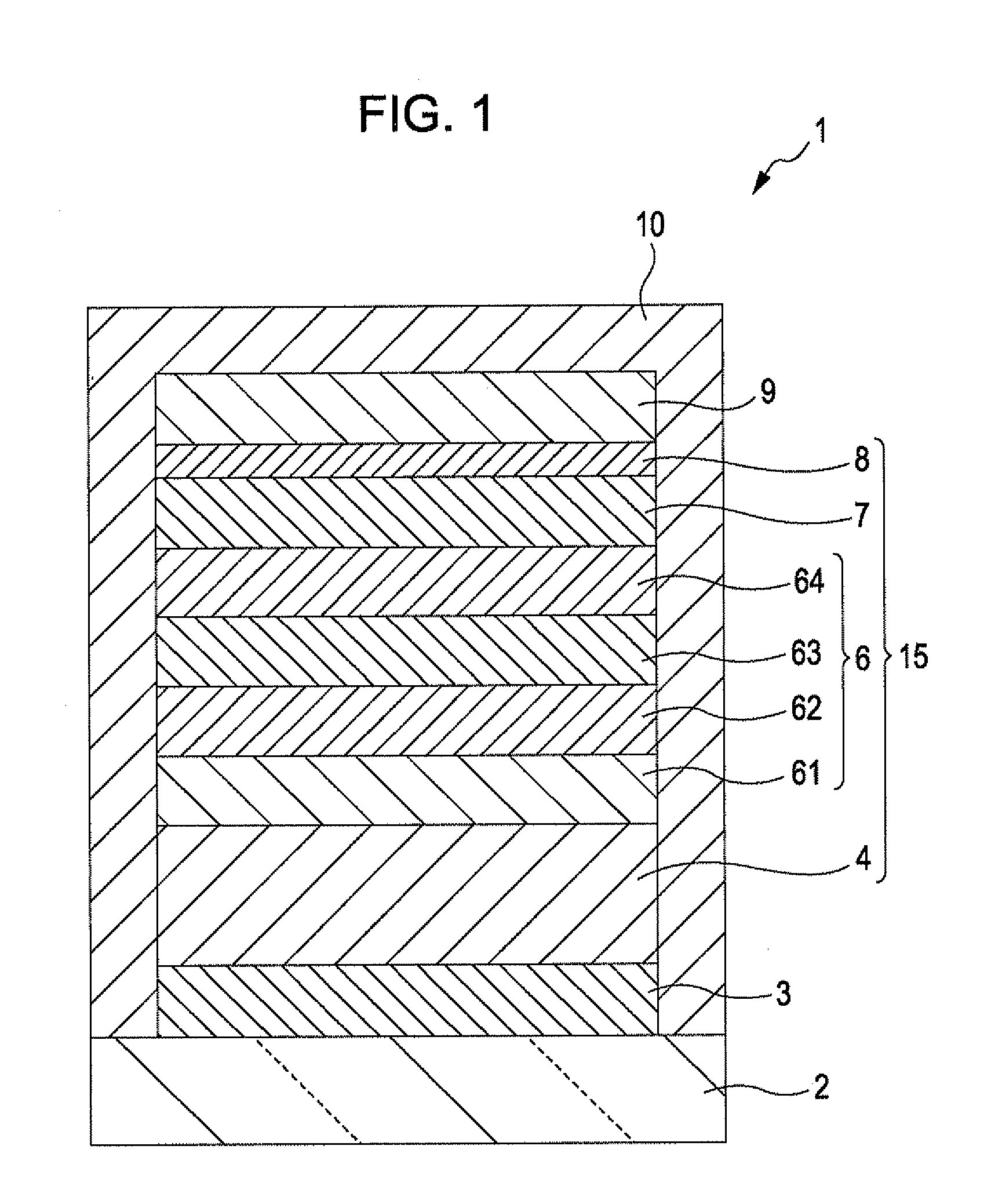
[0043]FIG. 1 is a schematic cross-sectional view of a light-emitting element according to Embodiment 1 of an aspect of the invention. Note that in the following description, for convenience, the upper side of FIG. 1 is simply referred to as the upper side, and the lower side of FIG. 1 is simply referred to as the lower side.

[0044]FIG. 1 illustrates a light-emitting element (EL element) 1, a white light-emitting element.

[0045]The light-emitting element 1 can be obtained by layering an anode 3, a hole-injection layer 4, a light-emitting portion 6, an electron-transport layer 7, an electron-injection layer 8, and a cathode 9 in this order. In other words, the light-emitting element 1 has a laminate 15 interposed between the anode 3 and the cathode 9, and the laminate 15 contains the hole-injection layer 4, the light-emitting portion 6, the electron-transport layer 7, and the electron-injection layer 8 layered in this order from the anode 3 side toward the cathode 9 side. The light-emit...

embodiment 2

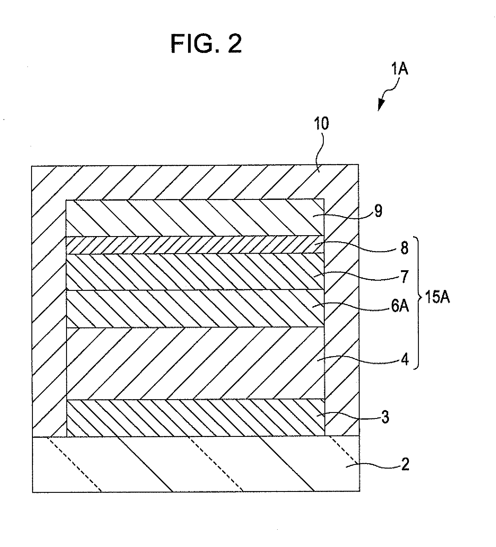
[0162]FIG. 2 is a schematic cross-sectional view of a light-emitting element according to Embodiment 2 of an aspect of the invention. Note that in the following description, for convenience, the upper side of FIG. 2 or the cathode 9 side is simply referred to as the upper side, and the lower side of FIG. 2 or the anode 3 side is simply referred to as the lower side.

[0163]The light-emitting element 1A, according to Embodiment 2, is equivalent to the light-emitting element 1, according to Embodiment 1, except that the light-emitting portion contains only a single light-emitting layer. The light-emitting element 1A has a laminate 15A interposed between an anode 3 and a cathode 9, and the laminate 15A contains a hole-injection layer 4, a light-emitting portion 6A, an electron-transport layer 7, and an electron-injection layer 8 layered in this order from the anode 3 side to the cathode 9 side.

[0164]The light-emitting portion 6A contains only a single light-emitting layer, and the light-...

example 1

[0195]I. A transparent glass substrate with an average thickness of 0.5 mm is coated by sputtering with an ITO electrode with an average thickness of 150 nm. This ITO electrode was for the use as a cathode. Subsequently, the substrate was sonicated in acetone and in 2-propanol and then treated with oxygen plasma and argon plasma. The conditions for plasma treatment were as follows regardless of sprayed element: substrate temperature: 70 to 90° C.; plasma power: 100 W; gas flow rate: 20 sccm; treatment duration: 5 seconds.

[0196]II. The ITO electrode was coated by vacuum deposition with the benzidine derivative expressed by Formula (4-3) until a film was obtained with an average thickness of 60 nm. The obtained film was for the use as a hole-injection layer.

[0197]III. The hole-injection layer was coated by vacuum deposition with materials of a red light-emitting layer (a first light-emitting layer) until a film was obtained with an average thickness of 7 nm. The materials used were th...


PUM


Abstract

A light-emitting element has a cathode, an anode, a light-emitting portion interposed between the cathode and the anode and having a light-emitting layer that emits light on energization between the cathode and the anode, and a hole-injection layer interposed between and in direct contact with the anode and the light-emitting layer and having a capability of receiving holes, and the hole-injection layer is mainly composed of a benzidine derivative.

Description

BACKGROUND[0001]1. Technical Field[0002]The present invention relates to a light-emitting element, a light-emitting apparatus, a display, and an electronic device.[0003]2. Related Art[0004]Organic electroluminescence (EL) elements are light-emitting elements each composed of an anode, a cathode, and at least one light-emitting organic layer interposed between them. An electric field is applied between the cathode and the anode, electrons and holes are injected from the cathode and the anode, respectively, to the light-emitting layer where they are coupled once again forming excitons, and then the excitons return to the ground state emitting energy in the form of light.[0005]An example of light-emitting elements is the one disclosed in Japanese Patent No. 3654909, a light-emitting element further having a hole-injection layer and a hole-transport layer interposed between an anode and a light-emitting layer in order for improved injection of holes.[0006]Recently, there has been demand...

Claims


Application Information

Patent Timeline
Patent Type & Authority Applications(United States)
IPC IPC(8): H01L51/52
CPCH01L27/322H01L51/5278H01L51/5048H10K59/38H10K50/14H10K50/19
Inventor FUJITA, TETSUJIYAMAMOTO, HIDETOSHIIWATA, SHINICHIYASUKAWA, KOJI
Owner SEIKO EPSON CORP
Why Eureka
Try Eureka