Liquid crystal display device

Inactive Publication Date: 2011-05-19
PANASONIC LIQUID CRYSTAL DISPLAY CO LTD +1
View PDF2 Cites 13 Cited by
  • Summary
  • Abstract
  • Description
  • Claims
  • Application Information

AI Technical Summary

Benefits of technology

[0035]According to the present invention, it is possible to provide a liquid crystal display device with light utilization efficiency of a b

Problems solved by technology

Further, in some case, in-plate distributions in the directions of the phase difference and the principal refractive index are not uniform.
Therefore, it is difficu

Method used


Image

  • Liquid crystal display device
  • Liquid crystal display device
  • Liquid crystal display device

Examples


first embodiment

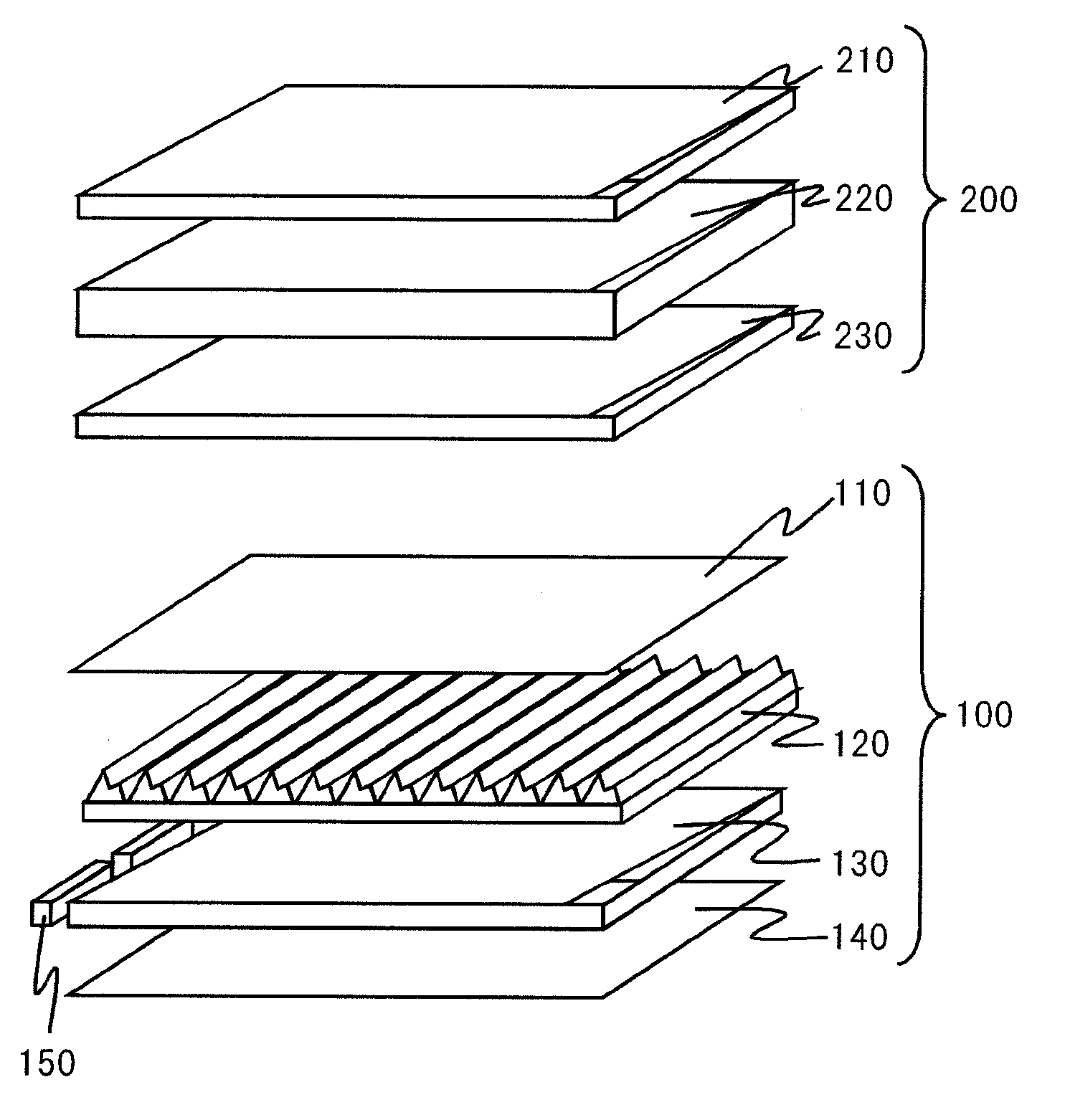
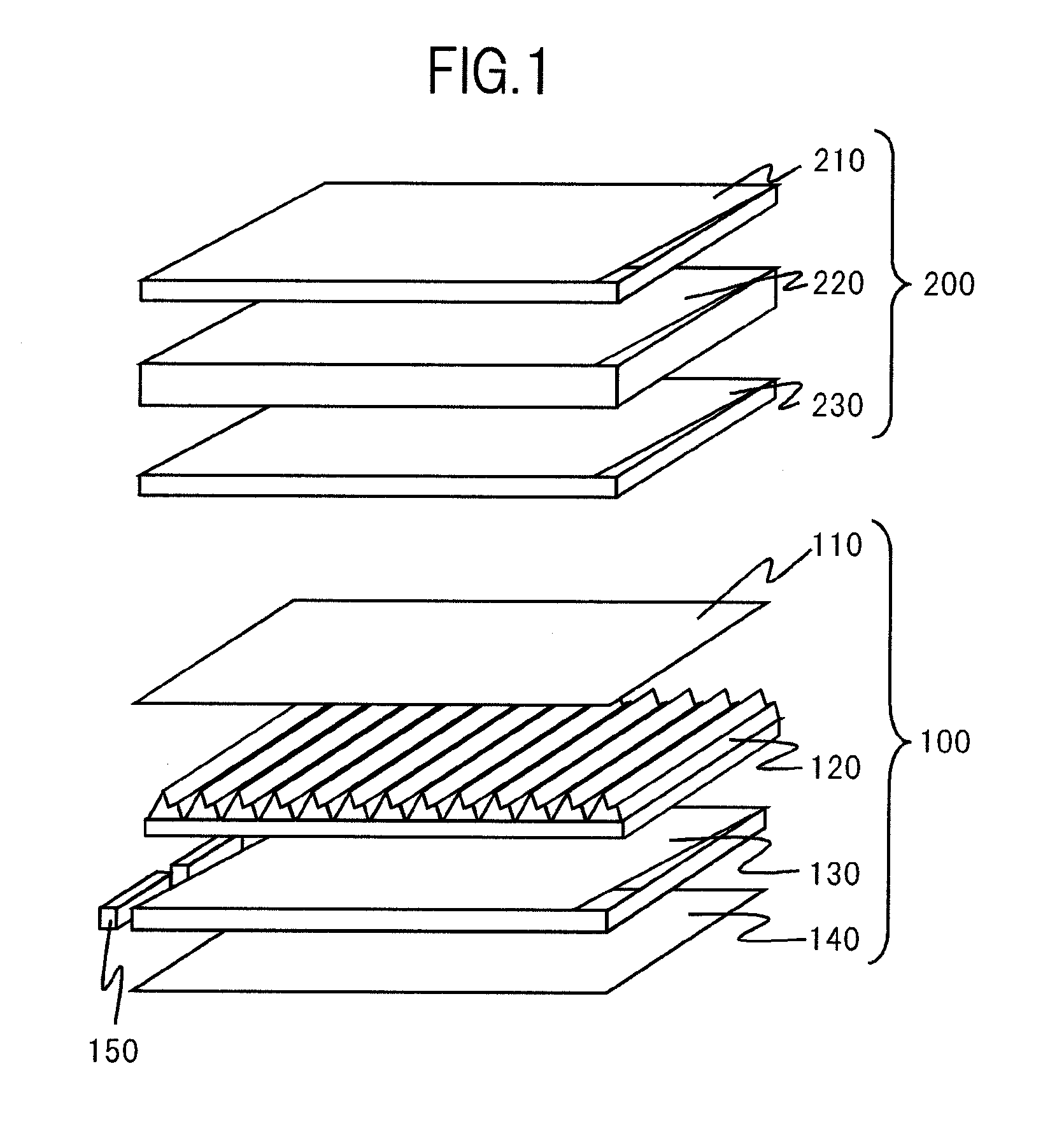
[0062]FIG. 1 is a diagram showing a state in which components included in a liquid crystal display device according to this embodiment are separated. As shown in the figure, the liquid crystal display device according to this embodiment includes a liquid crystal panel 200 and a surface light source (a back light) 100. The liquid crystal panel 200 includes a liquid crystal cell 220, an upper polarizer 210 provided on an observer side of the liquid crystal cell 220, and a lower polarizer 230 provided on the surface light source 100 side of the liquid crystal cell 220. The surface light source 100 includes a diffusion sheet 110, a prism sheet 120, a light guide plate 130, a reflective sheet 140, and a light source section 150.

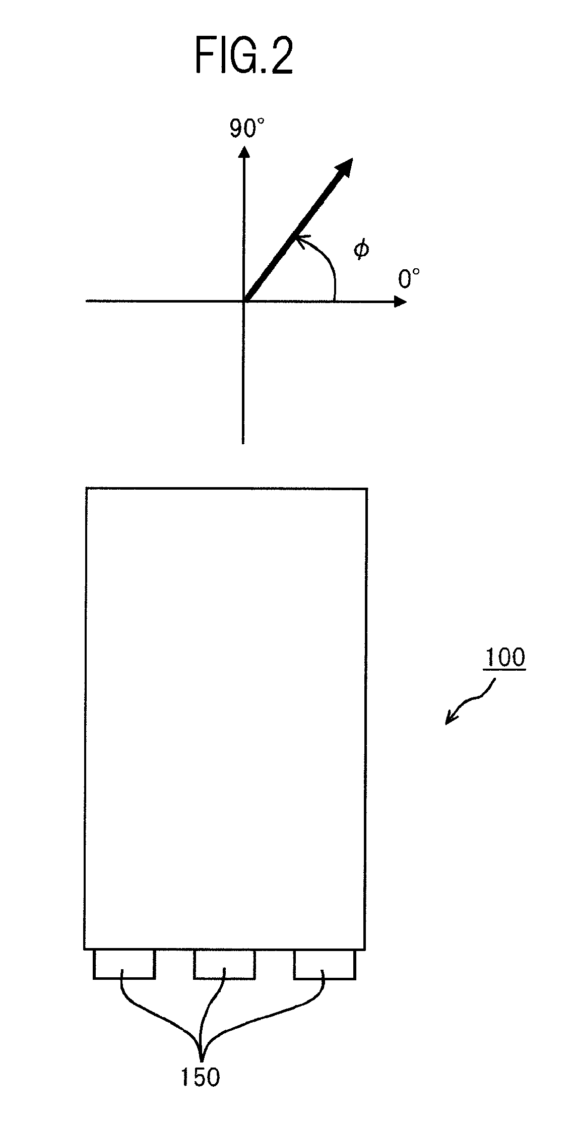
[0063]FIG. 2 is a plan view showing a schematic configuration of the surface light source 100 according to this embodiment. A definition of an azimuth angle φ is also written in the figure. As shown in the figure, a reference (0 degree) is provided in parallel to ...

second embodiment

[0097]A liquid crystal display device according to a second embodiment of the present invention is explained below.

[0098]This embodiment is different from the first embodiment in that, for example, a flat surface without a tilt is arranged between the prisms of the polarization converting sections 131 of the light guide plate 130 and in the shape of the emitting sections 132. Otherwise, this embodiment is substantially the same as the first embodiment. Explanation of similarities to the first embodiment is omitted.

[0099]FIG. 10A is a diagram showing a state in which a surface on the prism sheet 120 side of the light guide plate 130 according to this embodiment is faced up. FIG. 10B is a diagram showing a state in which a surface on the reflective sheet 140 side of the light guide plate 130 according to this embodiment is faced up. As shown in FIG. 10A, the polarization converting sections 131 are configured by forming prisms, each of which includes at least two slopes, in a row and ...

third embodiment

[0100]A liquid crystal display device according to a third embodiment of the present invention is explained below.

[0101]This embodiment is the same as the first embodiment in that the emitting sections 132 and the polarization converting sections 131 of the light guide plate 130 are provided on the reflective sheet 140 side and a shape for eliminating unevenness of a light source is provided on the prism sheet 120 side. Whereas the emitting sections 132 are provided among the prism rows as the polarization converting sections 131 to overlap the valley lines when viewed from the outer side of the light guide plate 130 in the first embodiment, in the third embodiment, the prism rows are arranged in a plurality of places at an interval in the light guide azimuth and the emitting sections 132 are formed among the prism rows discontinuously arranged. The third embodiment is different from the first and second embodiments at this point. Otherwise, this embodiment is substantially the same...


PUM


Abstract

A liquid crystal display device includes light source sections 150, a light guide plate 130 guiding light of the light source sections from a side edge and including a light emitting surface, and a liquid crystal panel 200 including a lower polarizer 230 opposed to the light emitting surface. The lower polarizer has a transmission axis generally along a light guide azimuth in which the light guide plate guides the light. The light guide plate includes a polarization converting section 131 on at least one of the light emitting surface and a rear surface. The polarization converting section reflects light made incident from the light guide azimuth in a different traveling azimuth and further reflects the light reflected in the different traveling azimuth to bring the traveling azimuth closer to the light guide azimuth to thereby convert polarization of the light traveling from the light guide azimuth.

Description

CROSS-REFERENCE TO RELATED APPLICATION[0001]The present application claims priority from Japanese application JP2009-259830 filed on Nov. 13, 2009, the content of which is hereby incorporated by reference into this application.BACKGROUND OF THE INVENTION[0002]1. Field of the Invention[0003]The present invention relates to a liquid crystal display device that guides light from a light source of a side light type and supplies the light to a liquid crystal panel.[0004]2. Description of the Related Art[0005]In general, a liquid crystal display device is thin, light, and low power consumption. Therefore, the liquid crystal display device is used as a display device for a wide range of electronic apparatuses such as a notebook personal computer, a portable information terminal, a cellular phone, a digital camera, a monitor for a computer, and a thin television.[0006]Unlike a self-emitting display device such as a cathode ray tube or a plasma display device, such a liquid crystal display d...

Claims


Application Information

Patent Timeline
IPC IPC(8): G02F1/1335
CPCG02F1/133528G02B6/0056G02B6/0053G02F2001/133607G02F1/133607
Inventor ARAKI, CHIEKOSUGITA, TATSUYAADACHI, MASAYA
Owner PANASONIC LIQUID CRYSTAL DISPLAY CO LTD
Why Eureka
Try Eureka