Semiconductor light source apparatus and lighting unit

Inactive Publication Date: 2011-05-19
STANLEY ELECTRIC CO LTD
View PDF15 Cites 153 Cited by
  • Summary
  • Abstract
  • Description
  • Claims
  • Application Information

AI Technical Summary

Benefits of technology

[0017]The presently disclosed subject matter has been devised in view of the above and other characteristics, desires, and problems in the conventional art. An aspect of the disclosed subject matter can include providing adjustable semiconductor light source apparatuses for various lighting units such as a projector, in which a color tone of an illumination light having a large amount of light intensity can be adjusted by changing a distance between an intersection of an

Problems solved by technology

However, because it is physically impossible to locate the three LEDs at the same position, each of the three LEDs is located at an appropriate interval with respect to each other.
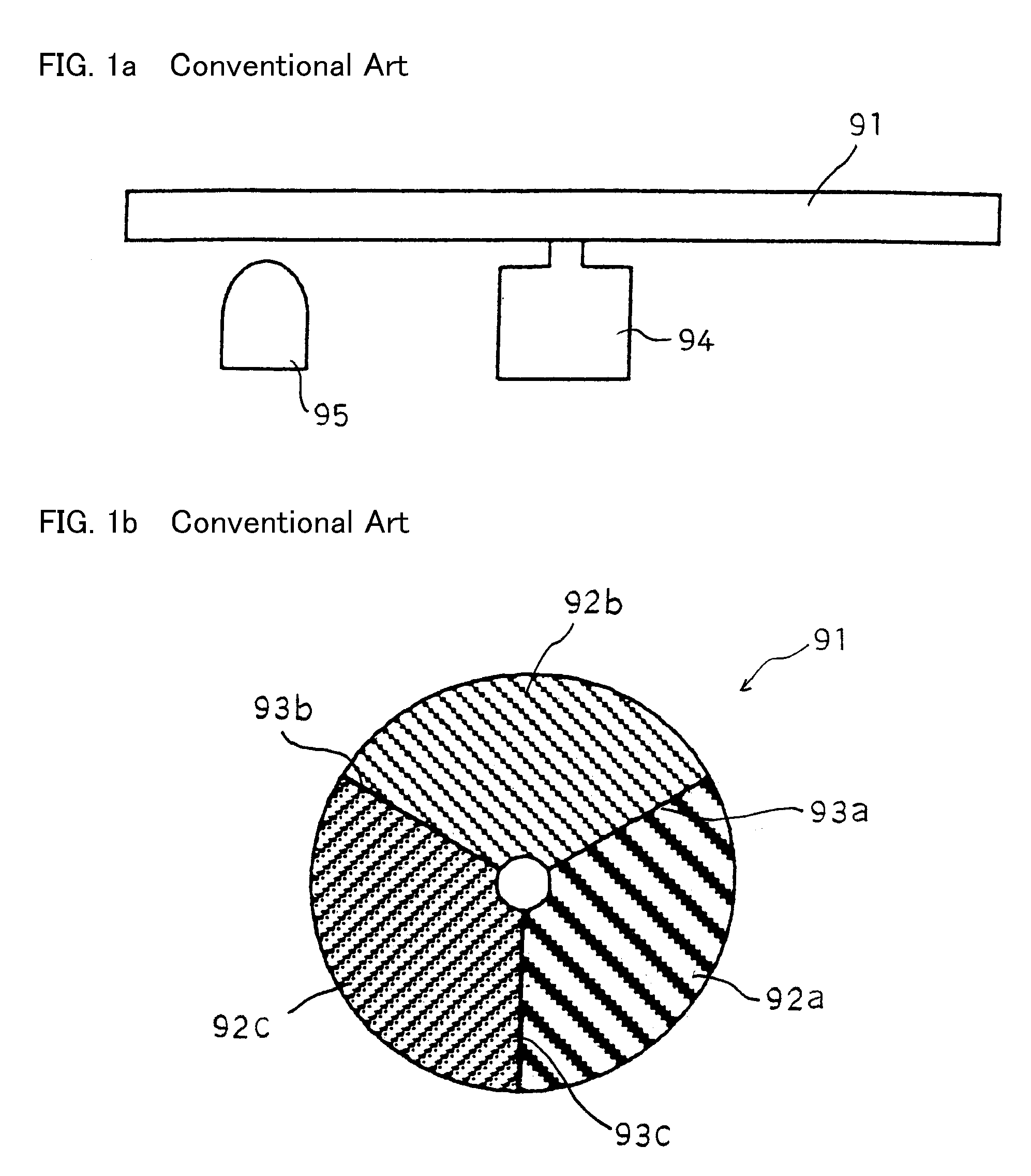
However, although the conventional light source apparatus using the phosphor wheel 91 may prevent color variation, it may not be able to adjust a color tone of light emitted from the semiconductor light source 95.
However, it may be difficult to contro

Method used


Image

  • Semiconductor light source apparatus and lighting unit
  • Semiconductor light source apparatus and lighting unit
  • Semiconductor light source apparatus and lighting unit

Examples


first embodiment

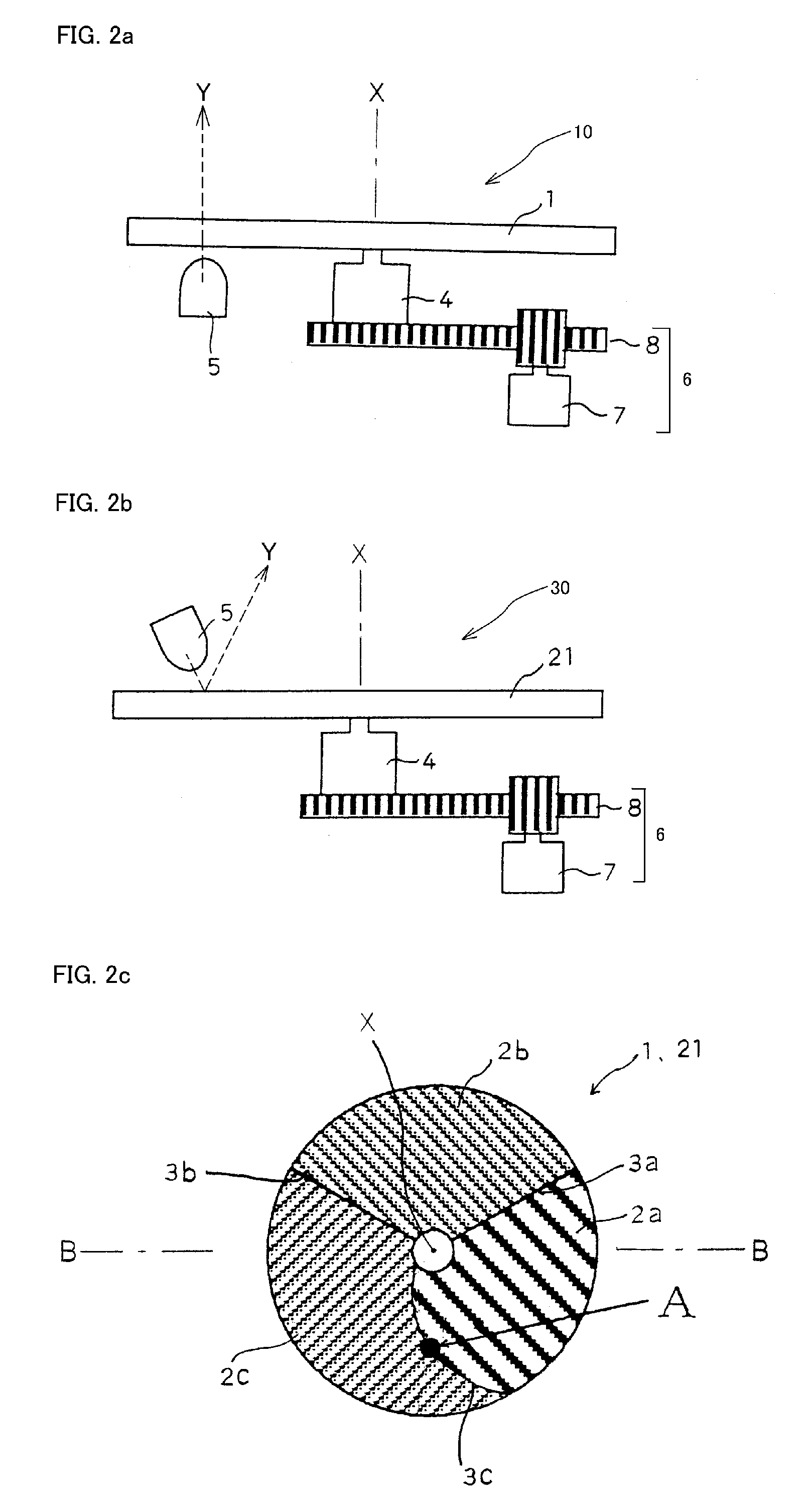
[0059]Variation of the first exemplary light source apparatuses 10 and 30 will now be described. A first variation of the first exemplary light source apparatuses 10 and 30 can vary in the semiconductor light source 5 and the phosphor wheels 1 and 21. Accordingly, in the first variation, the semiconductor 5 and phosphor wheels 41 and 61 will now be described in detail with reference to FIGS. 4a, 4b and 4c. As the semiconductor light source 5 of the first variation in the first embodiment, an LED of GaN series that emits blue light having a wavelength of approximately 460 nanometers can be used, and also a laser diode that emits blue light can be used, for example.

[0060]FIG. 4a is a schematic structural view showing a transmission / reflection type phosphor wheel of the first variation of the first exemplary semiconductor light source apparatuses, and FIGS. 4b and 4c are cross-sectional views depicting cross-sections taken along line C-C of the transmission and reflection type phosphor...

second embodiment

[0098]A second variation of the second exemplary light source apparatuses 10 and 30 can vary in the phosphor wheels 41 and 61 from the immediately above-described first variation. Accordingly, in this second variation of the second embodiment, phosphor wheels 78 and 80 will now be described in detail with reference to FIGS. 10a, 10b and 10c. FIG. 10a is a schematic structural view showing the transmission / reflection type phosphor wheel of the second variation of the second exemplary semiconductor light source apparatuses, and FIGS. 10b and 10c are cross-sectional views of the transmission and reflection type phosphor wheels depicted in FIG. 10a, respectively.

[0099]The transmission type phosphor wheel 78 can include a yellow phosphor layer 73 formed in a concentric, which wavelength-converts the blue light emitted from the semiconductor light source 5 into white light. In addition, the phosphor wheel 78 can include a transparent region 74 for transmitting the blue light without chang...

third embodiment

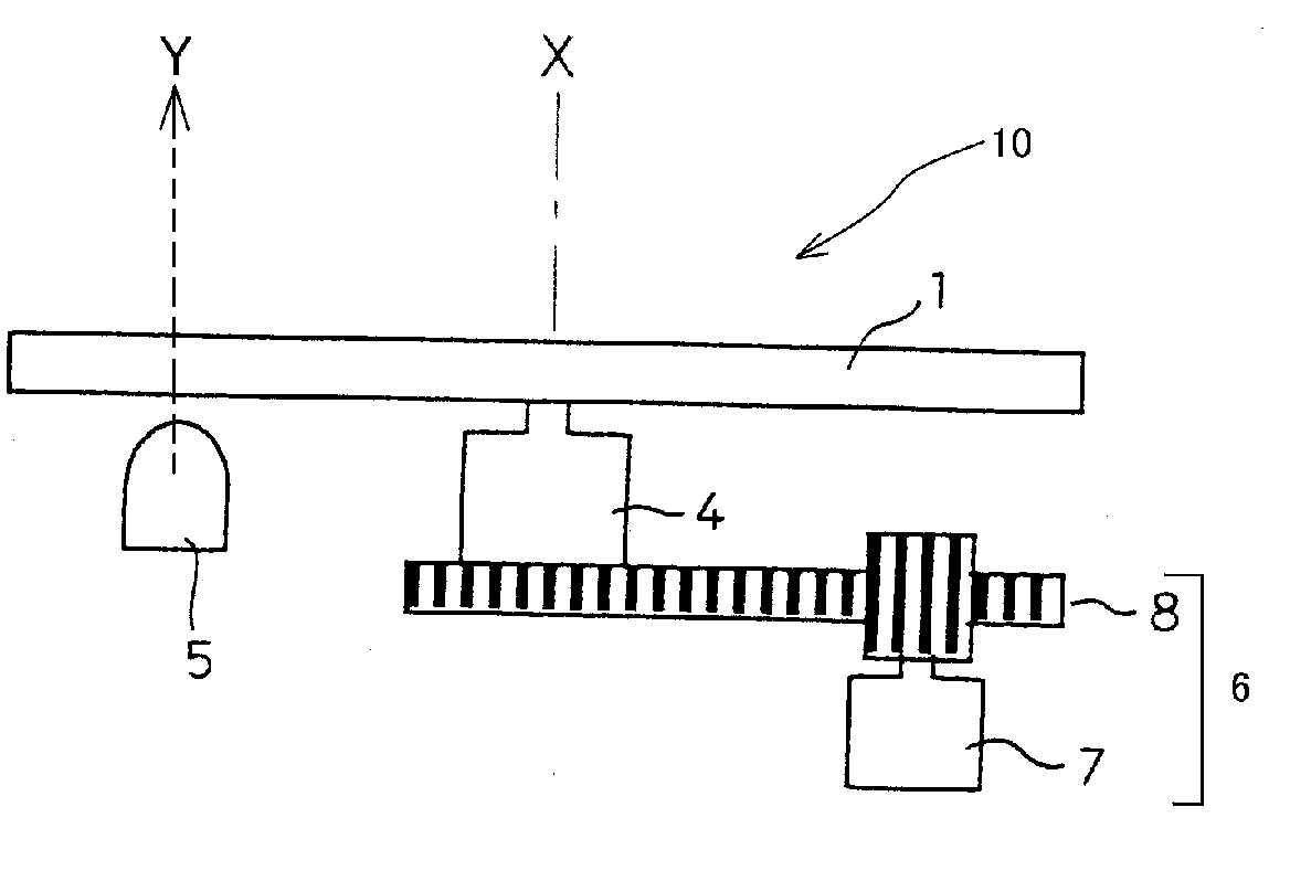
[0123]FIG. 14 is an explanatory diagram showing a relation between the semiconductor light source 5 and the yellow phosphor layers 32a, 32b and 32c in the first variation of the The semiconductor light source apparatus 10 including the phosphor wheel 44 can emit substantially white light due to an additive color mixture using the blue light emitted from the semiconductor light source 5 and lights excited by the three yellow phosphor layers 32a, 32b and 32c by rotating the phosphor wheel 41 with respect to the rotation axis X. When a light-emitting area of the semiconductor light source 5 is located so as to illuminate a light-emitting area U0 shown in FIG. 14, because each light-emitting area of the yellow phosphor layer 32a, 32b and 32c can substantially equal, the semiconductor light source apparatus 10 can emit a normal white light via the phosphor wheel 41.

[0124]Here, when the optical axis Y of the semiconductor light source 5 approaches the rotation axis X of the phosphor whee...


PUM


Abstract

A semiconductor light source apparatus can adjust a color tone of white light. The semiconductor light source apparatus can include a phosphor wheel, a motor rotating the phosphor wheel, a light source and a moving module. The phosphor wheel can include at least one phosphor layer configured to emit excited light. The phosphor wheel can vary a mixing ration of white light that is created by light emitted from the light source and the light excited by the at least one phosphor layer in accordance with a position of the phosphor wheel emitted by the light source. The moving module that is connected to the motor can adjust the position of light emitted from the light source. Thus, the disclosed subject matter can provide a semiconductor light source apparatus that can adjust a color tone of white light and a lighting unit using the light source apparatus, which can be used for a projector, lamp, etc.

Description

[0001]This application claims the priority benefit under 35 U.S.C. §119 of Japanese Patent Application No. 2009-262588 filed on Nov. 18, 2009, Japanese Patent Application No. 2009-263492 filed on Nov. 19, 2009, and Japanese Patent Application No. 2009-268330 filed on Nov. 26, 2009, all of which are hereby incorporated in their entireties by reference.BACKGROUND[0002]1. Field[0003]The presently disclosed subject matter relates to a semiconductor light source apparatus and a lighting unit using the semiconductor light source apparatus, and more particularly to a semiconductor light source apparatus that can change a color tone and a lighting unit that can also emit a large amount of light intensity while it can change a color tone in order to be able to use for a stage light, a street light, a projector, a vehicle light, a spot light, etc.[0004]2. Description of the Related Art[0005]Recently, semiconductor light source devices such as an LED and the like have been used as a light sour...

Claims


Application Information

Patent Timeline
IPC IPC(8): F21V9/16
CPCF21S10/007F21S10/02F21V5/008F21V5/048G03B21/204F21Y2101/02G02B26/007G03B11/00G03B21/14F21V9/10G03B33/08G03B21/005F21Y2115/10F21V9/45G02B26/008
Inventor SUGIYAMA, TAKASHI
Owner STANLEY ELECTRIC CO LTD
Why Eureka
Try Eureka