Servo Controller and Optical Disk Device

a technology of optical disk and servo controller, which is applied in the direction of digital signal error detection/correction, instruments, recording signal processing, etc., can solve the problems of servo operation failure, suppression gain is particularly insufficient for deviation components, and the following performance of servo controllers is improved, so as to improve the following performance of the track of the optical disk devi

Inactive Publication Date: 2011-05-19
HITACHI-LG DATA STORAGE +1
View PDF3 Cites 1 Cited by
  • Summary
  • Abstract
  • Description
  • Claims
  • Application Information

AI Technical Summary

Benefits of technology

[0034]According to the present invention, it is possible to improve the following performance of a servo controller and to improve the track following performance of an optical disk device.

Problems solved by technology

On the other hand, the disturbance components such as those of a defect and a scratch have a high frequency.
In the situation in which the following performance higher than that assumed by the standards is required as the servo performance of the optical disk device, there occurs an event in which the suppression gain is particularly insufficient for the deviation component.
In a worst case, the following operation cannot be appropriately carried out and the servo operation fails.
Even if the servo operation does not fail, since the following error becomes larger when a deviation is passed, the recording and reproducing performance is deteriorated.
However, in general, when the suppression performance is improved for a particular frequency range, the following performance is disadvantageously deteriorated for other frequency ranges.
Hence, it is feared that the following performance is deteriorated when a defect or a scratch is passed.
However, in the prior art, the deviation is detected on the basis of the servo error signal.
Hence, although the first point of the deviation area can be detected, it is not possible to detect the end point of the deviation area.
When the deviation is detected on the basis of the servo error signal to improve the suppression performance for the deviation component as in the detection method described above, a problem takes place.
That is, since the deviation component is too small, the area actually including the deviation cannot be detected in the method described above.
This leads to a problem in which even the end edge of the deviation area is passed, the event of the passing of the end edge cannot be detected.
It is difficult to restore to the steady-state characteristic in response to the end edge of the deviation area because of the increased servo gain.
However, this method is not available if the deviation area exists in two adjacent areas over a boundary between the two areas.
In this situation, if the servo characteristic is restored to the steady-state characteristic at timing at which the operation moves from the first area to the second area, the servo control fails in a worst case when the deviation is passed.
In a recording operation, this results in recording failure.
Therefore, it is similarly difficult to restore the characteristic from the characteristic in which the servo gain is increased after detection of the end edge of the deviation area to the steady-state characteristic.
Hence, in the prior art, there exists a problem in which it is not possible to change the servo characteristic only in the deviation area by detecting a deviation area.

Method used


Image

  • Servo Controller and Optical Disk Device
  • Servo Controller and Optical Disk Device
  • Servo Controller and Optical Disk Device

Examples


first embodiment

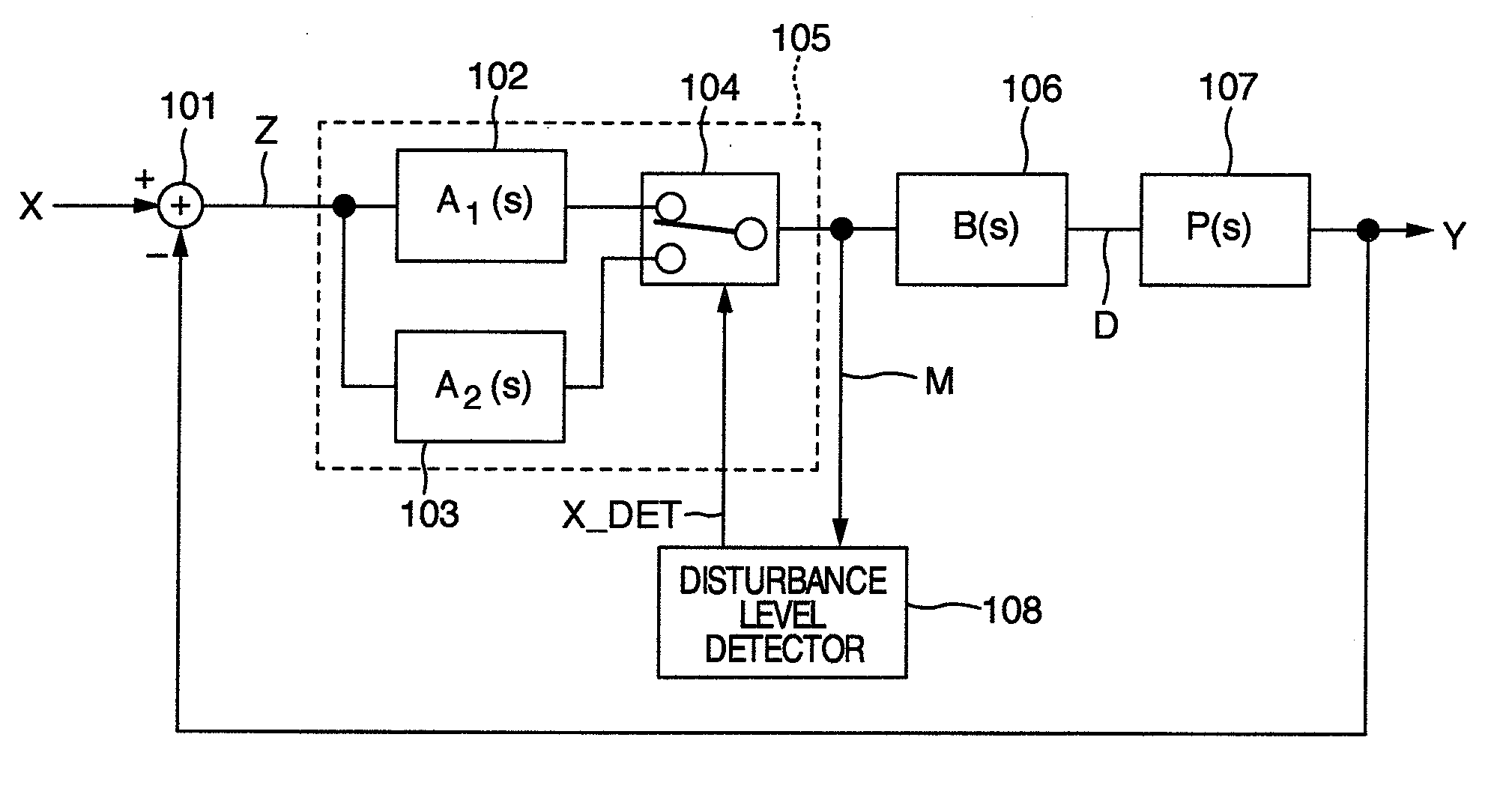
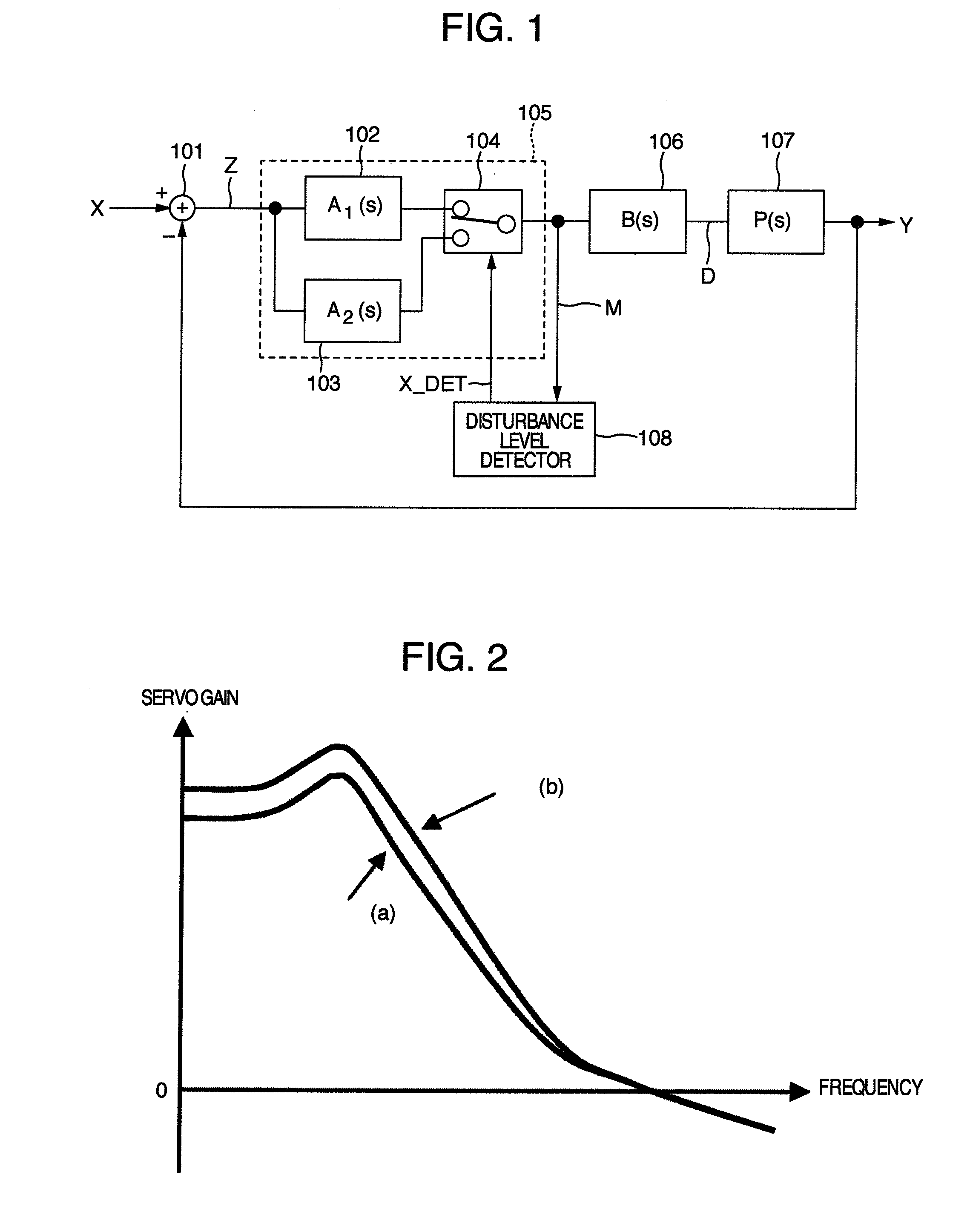
[0081]The present invention is applicable not only to the optical disk device, but also to any apparatus including a feedback control system. First, description will be given of the theory of the present invention by referring to a block diagram of a feedback control system shown in FIG. 1.

[0082]A variable X is disturbance inputted to a servo system. It is assumed in this system that only X is the disturbance to the feedback control system.

[0083]Reference numeral 101 is a subtractor. The subtractor 101 calculates the difference between the disturbance X and quantity of operation Y of a control object 106, which will be described later, and produces a following error Z.

[0084]Reference numeral 102 indicates a first control element. The first control element 102 compensates the gain or phase for the following error Z. The transfer function of the first control element 102 is represented as A1(s).

[0085]Reference numeral 103 indicates a second control element. The second control element ...

second embodiment

[0218]Description will now be given of a second embodiment.

[0219]In the configuration of the first embodiment, the deviation detector 414 receives the signal TE2 outputted from the adder 406. The deviation detector 414 of the first embodiment includes a band-pass filter 1201 having a frequency characteristic shown in FIG. 13.

[0220]At detection of a deviation, the deviation detector 414 increases the learning degree of the iterative learning control to suppress a deviation component. Hence, in the band-pass filter 1201, it is favorable that attenuation of the high-frequency component matches a frequency band for which the repetitive learning system has suppression effect.

[0221]In the signal REPOUT produced from the repetitive learning system, the high-frequency component has been attenuated by the low-pass filters 410 and 412 of the repetitive learning system. Hence, it is favorable that the attenuation of the high-frequency component through the band-pass filter 1201 is equivalent i...

third embodiment

[0236]Next, description will be given of a third embodiment.

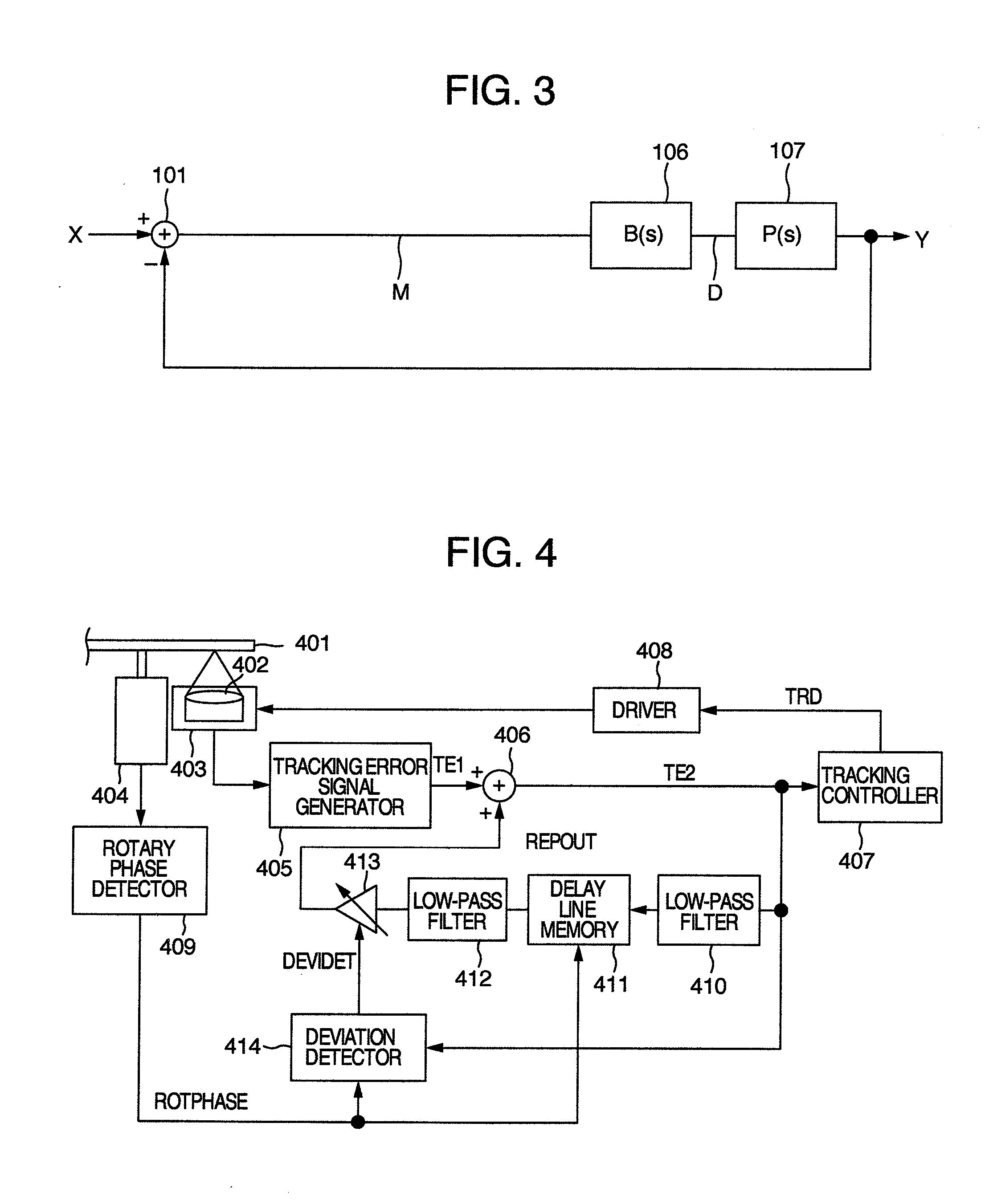
[0237]FIG. 24 shows an optical disk device according to the third embodiment.

[0238]In FIG. 24, the same constituent components as those of the first embodiment shown in the block diagram of FIG. 4 are assigned with the same reference numerals. Hence, description of the components will be avoided.

[0239]Reference numeral 416 indicates a third low-pass filter, which attenuates a high-frequency component contained in the signal TE2. The filter 416 has a cutoff frequency equal to or more than that of the first low-pass filter 410.

[0240]Reference numeral 417 indicates a first selector, which receives the output signals respectively from the first and third low-pass filters 410 and 416 to select either one thereof and outputs the selected signal. The first selector 417 selects the signal based on the deviation detection signal (DEVIDET) from the deviation detector 414.

[0241]In the third embodiment, the delay line memory 411 receiv...


PUM

PropertyMeasurementUnit
phaseaaaaaaaaaa
thresholdaaaaaaaaaa
electricaaaaaaaaaa

Abstract

In a servo controller and an optical disk device (FIG. 4), the following performance for disturbance is improved. By disposing a characteristic change section to change a characteristic to improve the following performance for disturbance, the disturbance is detected by use of a signal in a stage after the characteristic change section.

Description

INCORPORATION BY REFERENCE[0001]The present application claims priority from Japanese application JP2009-259431 filed on Nov. 13, 2009, the content of which is hereby incorporated by reference into this application.BACKGROUND OF THE INVENTION[0002]The present invention relates to a servo controller and an optical disk device to record or to reproduce information on an optical disk.[0003]In an optical disk device employing an optical disk, periodic external disturbance due to rotation of the optical disk is a factor to cause a servo following capability. Methods to improve the following performance to follow such periodic disturbance are described, for example, in JP-A-8-77589 and JP-A-2007-207390.[0004]According to JP-A-8-77589, for example, in the description of paragraph [0056], track deviation obtained for each of several preceding disk rotations is stored to be compared with the present track deviation. As a result of the comparison, a correlation is detected between the trackin...

Claims


Application Information

Patent Timeline
Patent Type & Authority Applications(United States)
IPC IPC(8): G11B7/12
CPCG11B7/0948G11B7/0941
Inventor ONOE, SHINSUKE
Owner HITACHI-LG DATA STORAGE
Why Eureka
Try Eureka