Dual direction exercise treadmill with moment arm resistance

Inactive Publication Date: 2011-05-19
ELLIS JOSEPH K
View PDF9 Cites 52 Cited by
  • Summary
  • Abstract
  • Description
  • Claims
  • Application Information

AI Technical Summary

Benefits of technology

[0019]Generally speaking, the internal mechanical components of the treadmill are similar to (or can be similar to or the same as) the internal mechanical components of known treadmills. The treadmill comprises an endless belt looped about rollers or pulleys so as to provide a platform on which the user can stand, walk and/or run. A deck below a portion

Problems solved by technology

However, with the exception of this inventor's inventions, this inventor is unaware of any specific exercise treadmill that is structured to

Method used


Image

  • Dual direction exercise treadmill with moment arm resistance
  • Dual direction exercise treadmill with moment arm resistance
  • Dual direction exercise treadmill with moment arm resistance

Examples


second embodiment

[0036]FIG. 5 is a side view of the moment arm weight resistance mechanism in the resting position. FIG. 6 is a side view of the moment arm weight resistance mechanism in a resistance position. FIG. 7 is a top view of an embodiment of the moment arm weight resistance mechanism of the invention. FIG. 8 is a side view of the embodiment of the moment arm weight resistance mechanism shown in FIG. 7. FIG. 9 is a side view of an alternate embodiment of the moment arm weight resistance mechanism of the invention. FIG. 10 is a sectional side view of the moment arm weight resistance mechanism shown in FIG. 3 in larger detail.

[0037]FIG. 11 is a sectional side view of a representative weight and weight adjusting drive that can be used with the present invention. FIG. 12 is a side view of the internal pulley and cable configuration between the resistance arm and the moment arm mechanism. FIG. 13 is a view of a representative control console and hand controller for the invention. FIG. 14 is a sid...

first embodiment

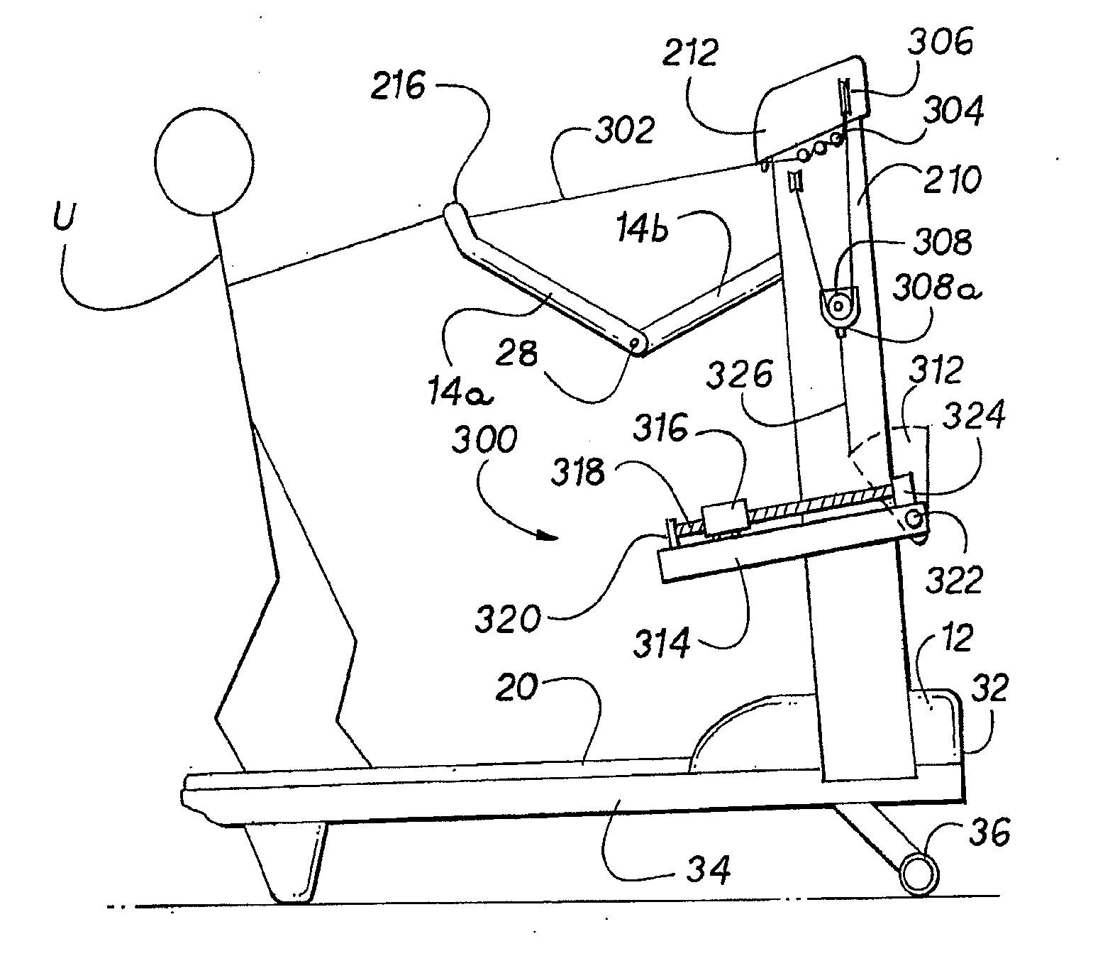
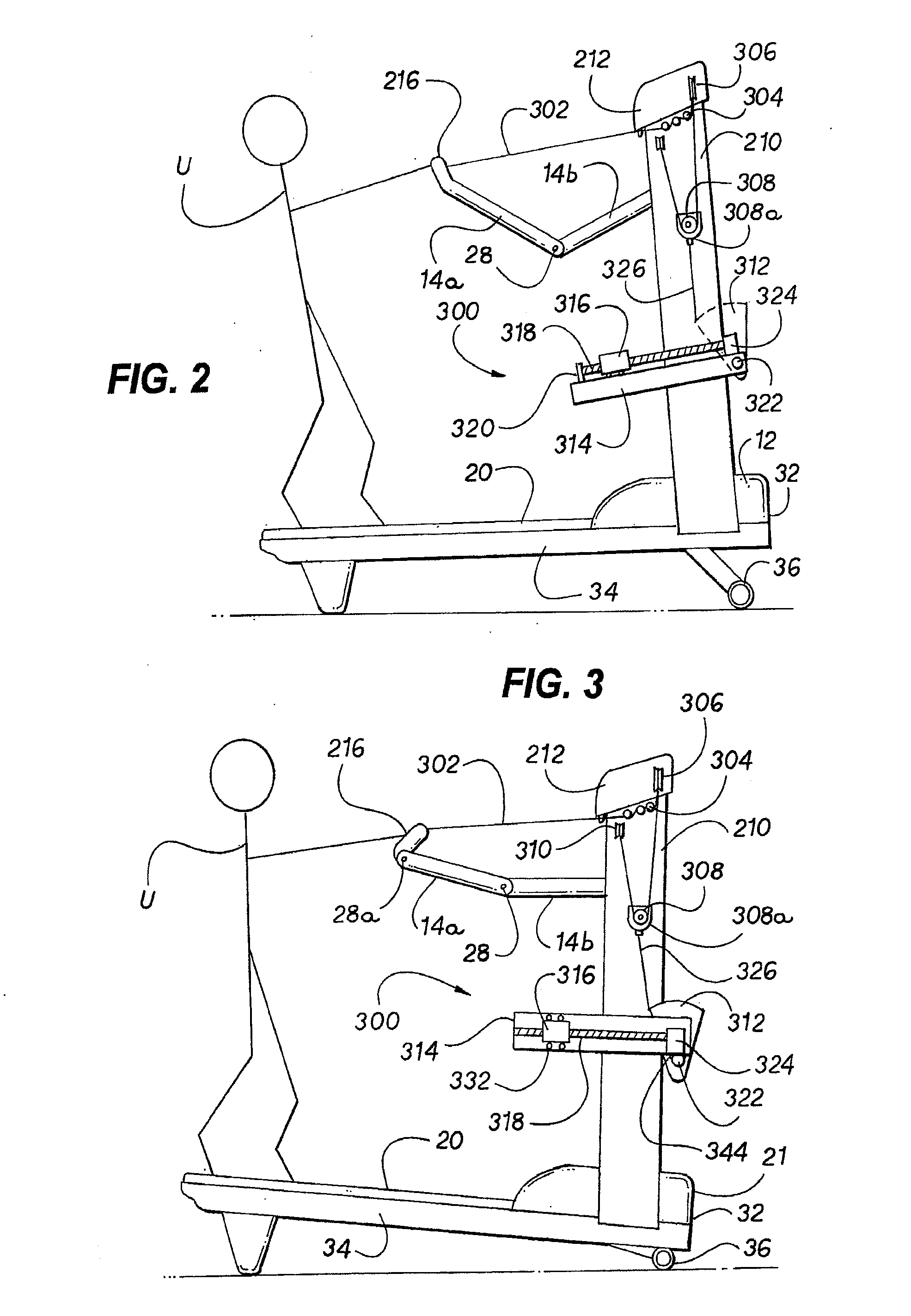
[0046]FIG. 2 is a side view of the treadmill 10 showing user U operating the treadmill 10 in a flat or level dragging or pulling simulation with a partial resistance arm 14 extension. In this position, user U is simulating a level surface dragging or pulling motion and is walking or running backwards and pulling on resistance arm 14, and thus pulling against moment arm weight resistance means 300. FIG. 2 shows the moment arm weight resistance mechanism 300 and a three-section resistance arm 14 in which the hand grip portion 216 is a part of the single upper resistance arm 14A. As can be seen, the multi-part structure of resistance arm 14 allows the appropriate motion of resistance arm 14 and hand controller 16 relative to user U for self-alignment of the resistance arm 14 and for proper and comfortable operation of treadmill 10. Moment arm weight resistance mechanism 300 is shown in an operating position, meaning moment arm weight resistance mechanism 300 is providing weight resista...


PUM


Abstract

An exercise treadmill for simulating a dragging or pulling action, having an endless moveable surface looped around rollers or pulleys to form an upper run and a lower run, with an exercise surface for walking or running on while operating the treadmill; and a moment arm weight resistance means for simulating the dragging or pulling of a load.

Description

BACKGROUND OF THE INVENTION[0001]1. Technical Field[0002]This invention relates to the general technical field of exercise, physical fitness and physical therapy equipment and machines and to the more specific technical field of conventional treadmills, dual-direction treadmills that can be operated in both a forward walking and running mode and a reverse dragging and pulling mode, and reverse dragging and pulling exercise machines, when operated by the user. This invention also relates to the more specific technical field of using a moment arm mechanism to generate weight resistance for simulating the dragging and pulling of a load.[0003]2. Prior Art[0004]Exercise, physical fitness and physical therapy equipment and machines are available in various configurations and for various purposes, and are available for all of the major muscle groups. The majority of such equipment and machines, especially in the exercise field, concentrate either on an aerobic or anaerobic workout or on ar...

Claims


Application Information

Patent Timeline
IPC IPC(8): A63B22/02
CPCA63B21/1434A63B21/1469A63B21/155A63B22/001A63B22/0023A63B22/02A63B21/0615A63B23/03575A63B23/047A63B24/00A63B2021/0616A63B2022/025A63B2022/0278A63B22/0235A63B21/0616A63B21/4017A63B21/4035A63B22/025
Inventor ELLIS, JOSEPH K.
Owner ELLIS JOSEPH K
Why Eureka
Try Eureka