Capacitive liquid level sensor

a liquid level sensor and capacitive technology, applied in liquid/fluent solid measurement, instruments, machines/engines, etc., to achieve the effect of compact sensor, better measurement precision, and equal manufacturing cos

Inactive Publication Date: 2011-05-26
INERGY AUTOMOTIVE SYST RES (SA)
View PDF2 Cites 49 Cited by
  • Summary
  • Abstract
  • Description
  • Claims
  • Application Information

AI Technical Summary

Benefits of technology

[0009]One object of the invention is to provide a capacitive sensor offering a better measurement precision a...

Problems solved by technology

This is because the sensors of the prior art either do nothing to overcome this undesirable influence, or they use a guard ring, such as for example the device from French Patent Application FR 2 647 898, or earthing strips, such as for example in the sensor from International Application WO 99/10714 (wh...

Method used


Image

  • Capacitive liquid level sensor
  • Capacitive liquid level sensor
  • Capacitive liquid level sensor

Examples


Embodiment Construction

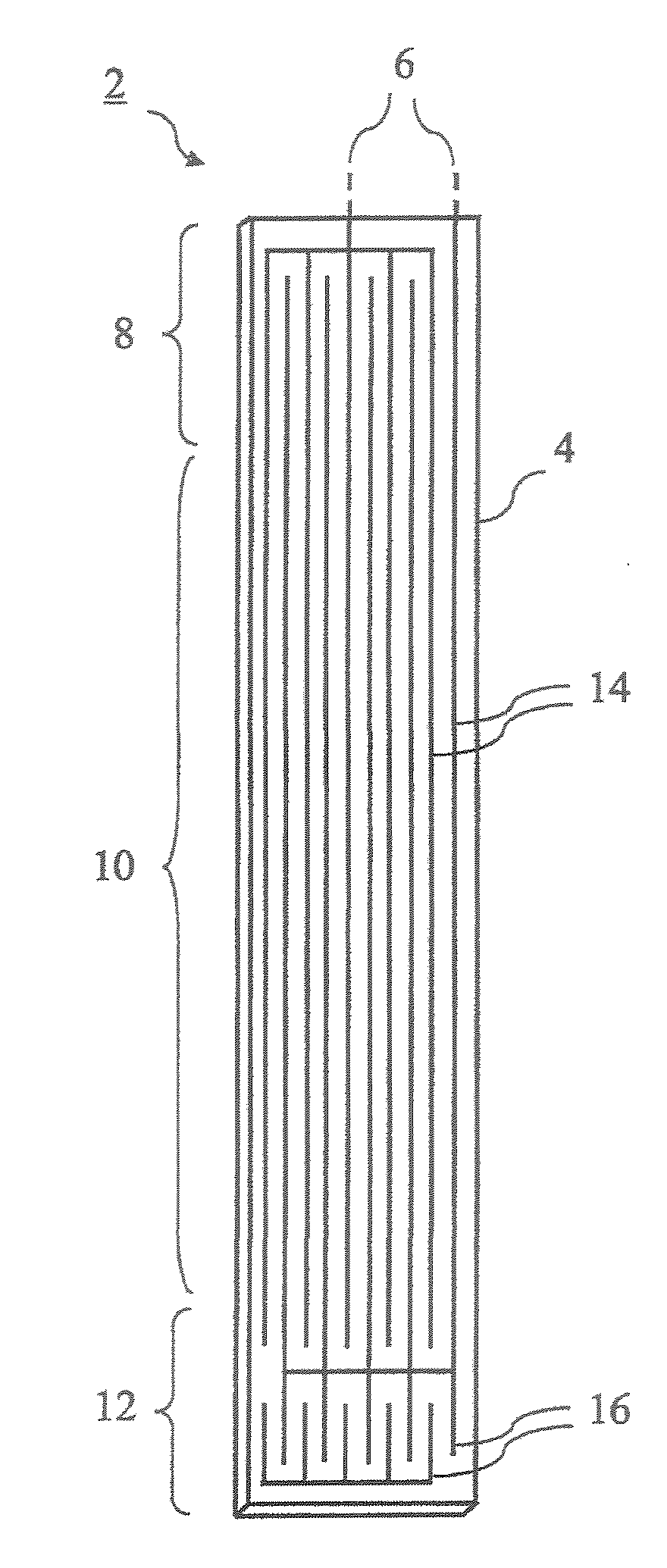
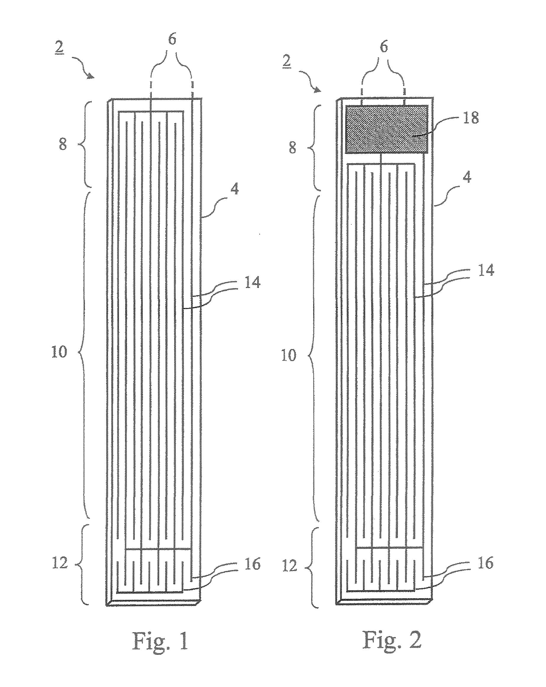
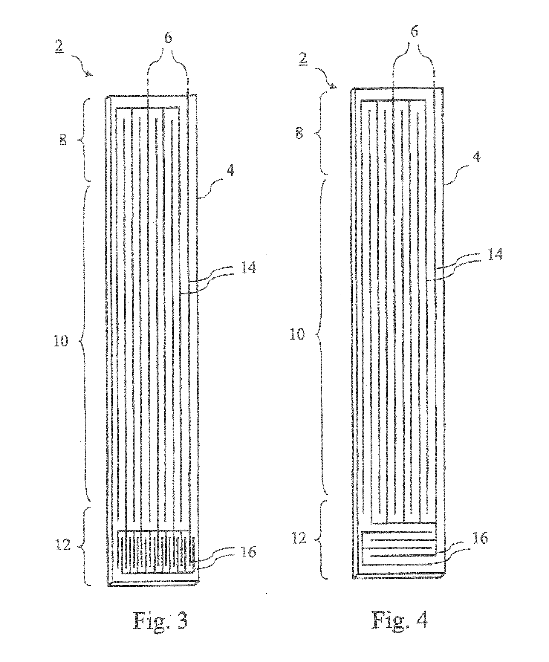
[0039]FIG. 1 shows a schematic view of one particular embodiment of the sensor 2 according to the invention, on which the presence of electrodes on a support 4 of the sensor 2 is illustrated. Two pairs of electrodes are represented on the support, these two pairs having one electrode in common. The three electrodes are each composed of parallel aims together forming interdigitated or interleaved combs. The measurement pair 14 is placed in the proximal 8 and central 10 parts of the support 4 and the reference pair 16 is placed in the distal part 12.

[0040]One of the two electrodes of the reference pair 16, and more specifically the electrode that is not common to the measurement pair 14, is linked to the connection means 6 by a connection line 26 that is not shown, and is located in an inner layer 24 of the support 4. This connection line 26, or supply line, is linked to the reference pair 16 by a connection passing through the insulating layer 20.

[0041]The reference pair 16 is intend...


PUM


Abstract

The invention relates to a capacitive sensor (2) for detecting the level (52) of a liquid (54) in a tank (48). The inventive sensor consists of: a flat longitudinal support (4) comprising proximal (8), central (10) and distal (12) parts and connection means (6) which are located in the proximal part (8) and which are used to connect the support (4) and the exterior of the support (4) electrically; a measuring pair (14) comprising interdigital arms which are disposed on the support (4) at least in the central part (10) thereof; and a reference pair (16) comprising interdigital arms which are disposed on the support (4) in the distal part (12) thereof. The aforementioned support (4) comprises at least three layers, and the reference pair (16) is linked to at least one connection track (26) which is located in an inner layer (24) of the support (4) and which is linked to the above-mentioned connection means (6). The invention also relates to a tank (48) comprising one such sensor (2).

Description

FIELD OF THE INVENTION[0001]The invention relates to a capacitive sensor for the liquid level of a tank, including a longitudinal and substantially flat support, intended to be positioned in the tank, the support including a proximal part, a central part and a distal part; and connection means, located in the proximal part, to electrically connect the support and the outside of the support; a first pair of electrodes, known as a measurement pair, including arms that are interdigital and positioned on the support, at least in its central part; and a second pair of electrodes, known as a reference pair, including arms that are interdigital and positioned on the support in its distal part.[0002]The invention relates, in addition, to a tank including such a sensor.PRIOR ART[0003]Such capacitive sensors are already known in the prior art.[0004]For example, U.S. Pat. No. 4,296,630 describes an apparatus for measuring the level of a fluid in a container by the use, on a stripline, of measu...

Claims


Application Information

Patent Timeline
IPC IPC(8): G01F23/26
CPCG01F23/268G01F23/266G01F23/26
Inventor BARLESI, LORENZOCHIAFFI, MICHELNAYDENOV, VOLODIA
Owner INERGY AUTOMOTIVE SYST RES (SA)
Why Eureka
Try Eureka