Single absorber vessel to capture co2

Active Publication Date: 2011-05-26
GENERAL ELECTRIC TECH GMBH
View PDF51 Cites 23 Cited by
  • Summary
  • Abstract
  • Description
  • Claims
  • Application Information

AI Technical Summary

Benefits of technology

[0049]The disclosed CO2 capture method allows the operating conditions of each absorption stage to be varied within a wide range. For example, one or more absorption stages may be operated under conditions resulting in the formation of solids, while one or more absorption stages are operated under conditions not resulting in precipitation of solids. The method facilitates recycling of used ionic solution within the absorber vessel since ionic solution from one or more absorption steps having similar composition and properties may be collected in a first sump vessel, while ionic solution from one or more other absorption steps having similar composition and properties, different to the composition and properties of the ionic solution collected in the first sump vessel, may be collected in a second sump vessel. For example, ionic solution from absorption steps resulting in the form

Problems solved by technology

A potential drawback associated with the NH3 based absorption systems and processes of the prior art is that solids, such as ammonium carbonate and/or bicarbonate,

Method used


Image

  • Single absorber vessel to capture co2
  • Single absorber vessel to capture co2

Examples


Embodiment Construction

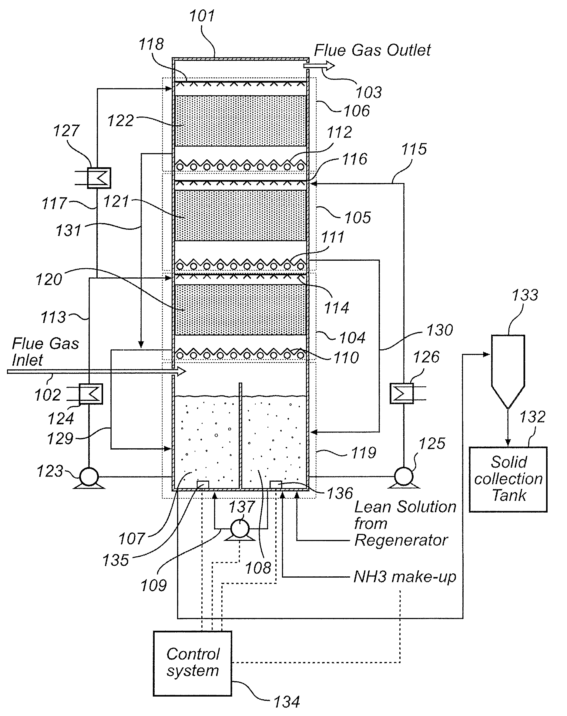
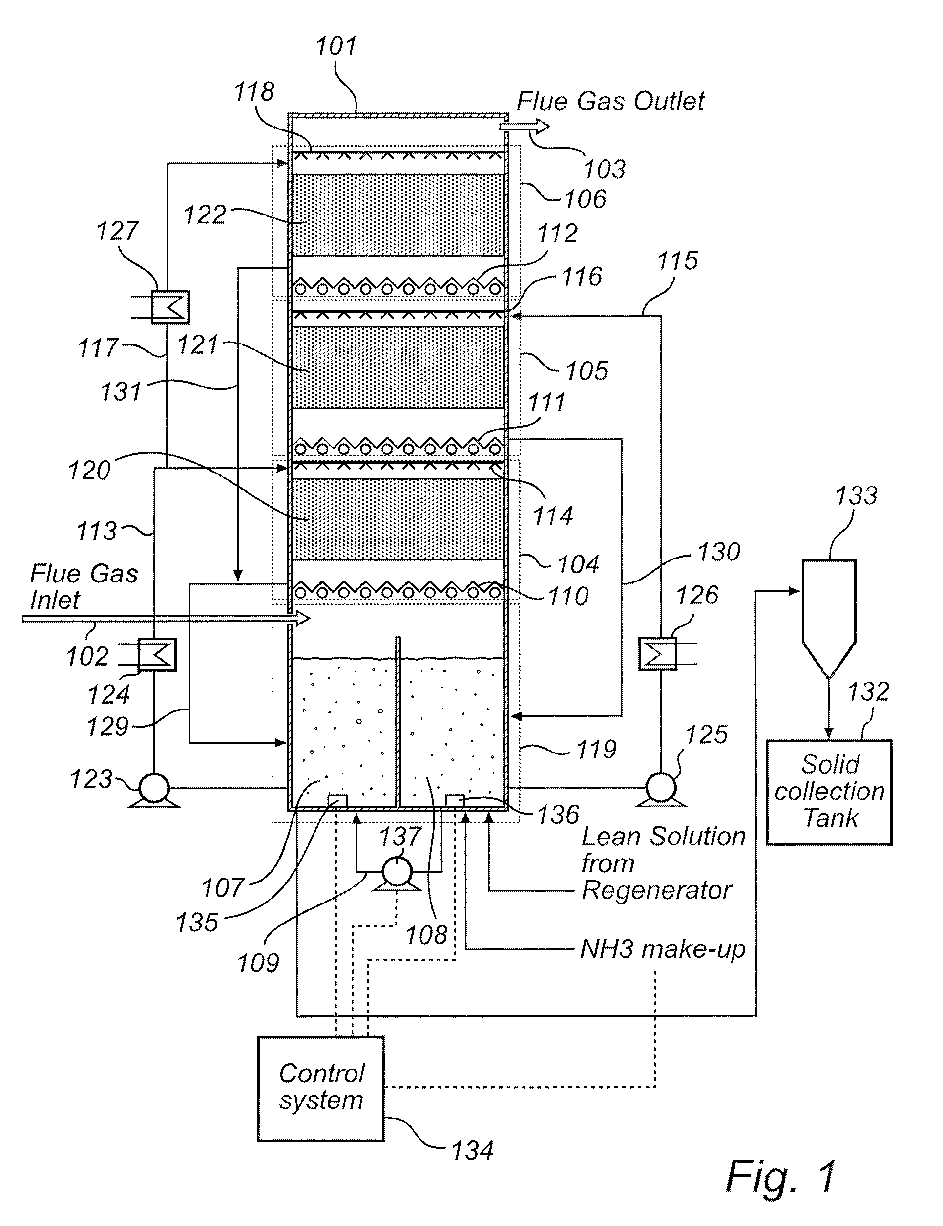
[0065]One embodiment of the proposed invention is generally depicted in FIG. 1. In this embodiment, a CO2 capture system is provided that includes three (3) absorption stages. It is, however, possible to include more or fewer absorption stages in the capture system without departing from the scope or spirit of the present invention.

[0066]Referring to FIG. 1 a single absorber vessel 101 is provided. The absorber vessel 101 is configured to receive a flue gas stream FG via an inlet 102 located near the bottom of the vessel 101 and to allow the flue gas stream FG to pass upward and through the absorber vessel 101 to exit via an outlet 103 located near the top of the vessel 101.

[0067]The flue gas stream FG entering the absorber vessel 101 will typically contain less than one percent moisture and low concentrations of SO2, SO3, HCl, and particulate matter (PM) which will typically be removed via air pollution control systems (not shown) upstream from the CO2 capture system. For example, ...


PUM

PropertyMeasurementUnit
Temperatureaaaaaaaaaa

Abstract

A system for removing carbon dioxide from a flue gas stream is provided, the system comprising an absorber vessel configured to receive a flue gas stream, the absorber vessel comprising a first absorption stage configured to receive the flue gas stream and contact it with a first ionic solution, a second absorption stage configured to receive flue gas which has passed the first absorption stage and contact it with a second ionic solution, a first sump vessel, and a second sump vessel. Furthermore, a method for removing CO2 from a flue gas stream containing CO2 is provided, the method comprising the steps of a) contacting a flow of a first ionic solution comprising NH3 with a flue gas stream to remove a first portion of CO2 from the flue gas stream, b) collecting the used ionic solution from step a) in a first sump vessel, c) recycling ionic solution from the first sump vessel to step a), d) contacting a flow of a second ionic solution comprising NH3 with the flue gas stream to remove a second portion of CO2 from the flue gas stream, e) collecting the used ionic solution from step d) in a second sump vessel, and f) recycling ionic solution from the second sump vessel to step d).

Description

FIELD OF THE INVENTION[0001]The present invention relates to a system and method for removing carbon dioxide from a flue gas stream using a multi-stage absorber vessel.BACKGROUND[0002]In the combustion of a fuel, such as coal, oil, peat, waste, etc., in a combustion plant, such as a power plant, a hot process gas is generated, often referred to as a flue gas, containing, among other components, carbon dioxide, CO2. The negative environmental effects of releasing carbon dioxide to the atmosphere have been widely recognized, and have resulted in the development of systems and processes adapted for removing carbon dioxide from the hot process gas generated in the combustion of the above mentioned fuels.[0003]One system and process previously disclosed is a single-stage Chilled Ammonia based system and method for removal of carbon dioxide (CO2) from a post-combustion flue gas stream. Such a system and process has been proposed and taught in published US Patent Application 2008 / 0072762 e...

Claims


Application Information

Patent Timeline
IPC IPC(8): B01D53/62B01D53/14B01D53/75
CPCB01D53/1406B01D53/1425B01D53/1475B01D53/62Y02C10/06B01D2257/504B01D2258/0291Y02C10/04B01D2252/102Y02A50/20Y02C20/40
Inventor DUBE, SANJAY K.HIWALE, RAMESHAWAR S.KOSS, PETER U.MURASKIN, DAVID J.
Owner GENERAL ELECTRIC TECH GMBH
Why Eureka
Try Eureka