Self-cooling exhaust gas recirculation device for an internal combustion engine

Active Publication Date: 2011-05-26
MANN HUMMEL GMBH
View PDF11 Cites 7 Cited by
  • Summary
  • Abstract
  • Description
  • Claims
  • Application Information

AI Technical Summary

Benefits of technology

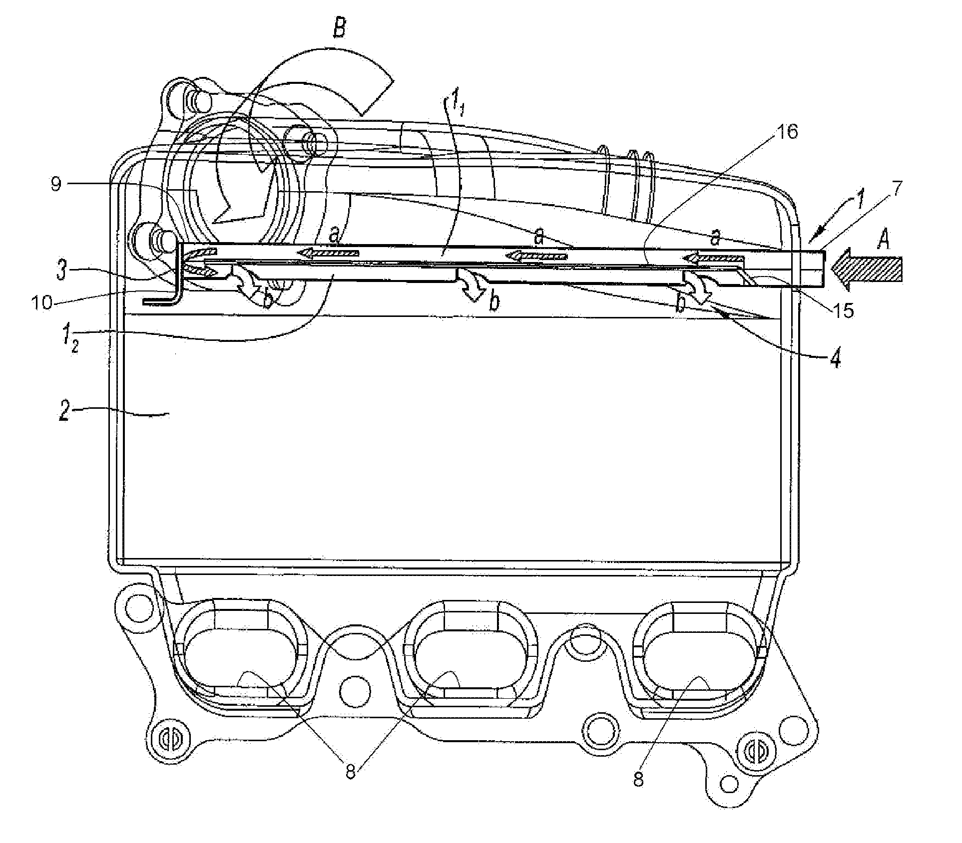
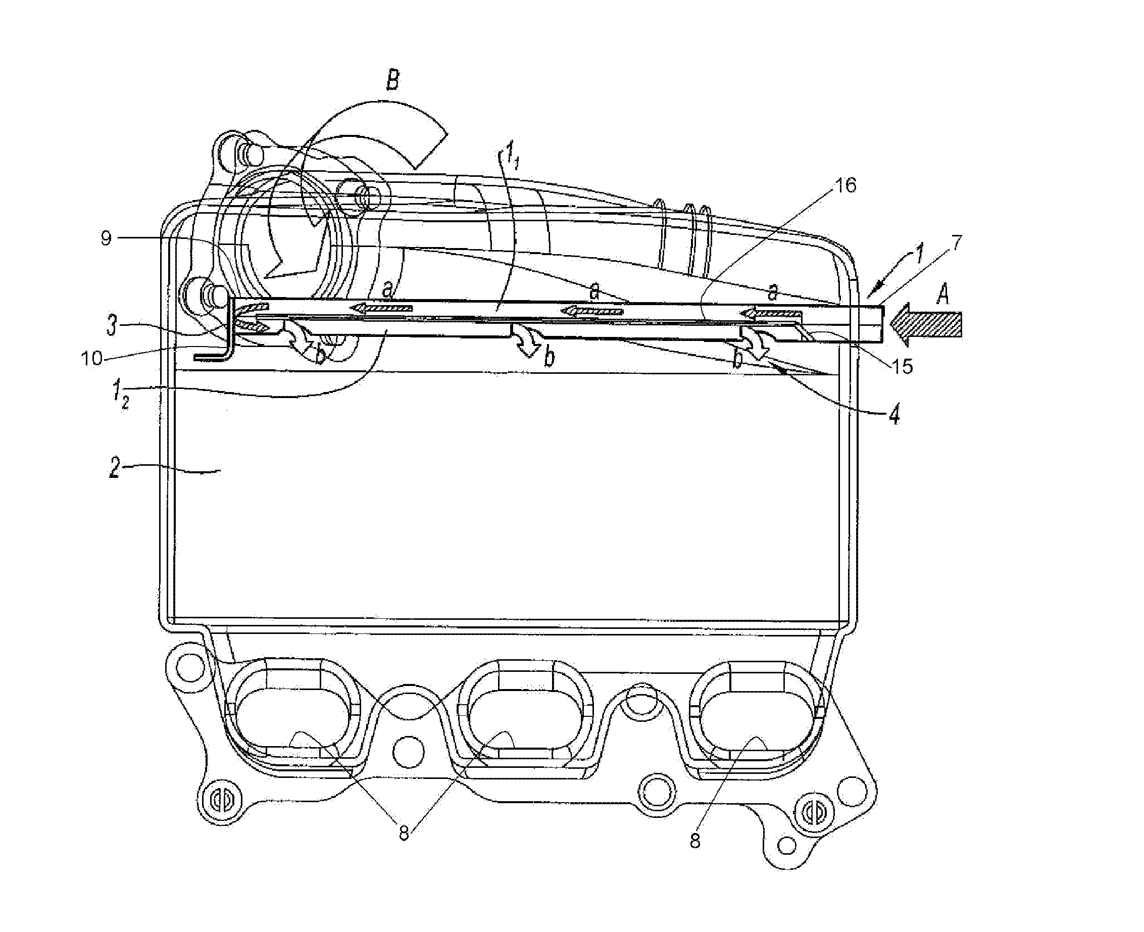
[0013]It is an object of the present invention to provide an exhaust gas recirculation device configured to use fresh air supplying the engine air intake distributor (also called an intake manifold) in order to provide passive cooling of the recycled gases, thereby freeing the EGR device from the presence of an additional heat exchanger for cooling these gases.
[0015]The exhaust gas return pipe advantageously continues, at its downstream end, into the internal part of the intake distributor by a first segment making it possible to cool the recycled gasses, and then by a second segment equipped with outlet orifices making it possible to introduce the gasses thus cooled into the intake distributor.
[0017]Beyond the possibility of directly introducing the recycled gasses into the intake distributor, without prior cooling, the device conforming to the invention has the advantage of making it possible to use a plastic distributor, therefore less costly, in particular in the case of diesel engines in which, without cooling, the recycled gasses would increase the internal temperature of the distributor to about 250° C.
[0019]Independently of the proceeding, many engines, both diesel and gasoline, are equipped with turbochargers which make it possible to meaningfully increase the quantity of gaseous mixtures supplying the cylinders and therefore the engine power.
[0023]In the case of an engine thus equipped, the device conforming to the invention makes it possible to use this cooling element for cooling not only the compressed air coming from the turbocharger, but also the recycled gasses.

Problems solved by technology

Such pollution limiting regulations tend to become stricter over time.
Further, the presence of an EGR device leads to a limitation of the quantity of oxygen present in the cylinders.
Engine exhaust gas recirculation however has the disadvantage of increasing the production of polluting particles, particularly in the case of diesel engines.
However, the presence of a heat exchanger has the disadvantage of notably increasing the cost of the EGR devices.

Method used


Image

  • Self-cooling exhaust gas recirculation device for an internal combustion engine
  • Self-cooling exhaust gas recirculation device for an internal combustion engine

Examples


Embodiment Construction

[0036]Before describing in detail embodiments that are in accordance with the present invention, it should be observed that the embodiments reside primarily in combinations of method steps and apparatus components related to an exhaust gas recirculation device for an internal combustion engine. Accordingly, the apparatus components have been represented where appropriate by conventional symbols in the drawings, showing only those specific details that are pertinent to understanding the embodiments of the present invention so as not to obscure the disclosure with details that will be readily apparent to those of ordinary skill in the art having the benefit of the description herein.

[0037]In this document, relational terms such as first and second, top and bottom, and the like may be used solely to distinguish one entity or action from another entity or action without necessarily requiring or implying any actual such relationship or order between such entities or actions. The terms “c...


PUM


Abstract

A self-cooling exhaust gas injection device making it possible to inject heated gases, for example recycled exhaust gases from an internal combustion engine, into the air intake distributor of this engine, characterized in that it comprises a return pipe for the exhaust gases (1) which extends in the distributor (2) to the downstream end thereof in the direction of the transfer of the recycled gasses and is equipped in this area with a series of outlet orifices (4) positioned so as to uniformly distribute these gases between each of the cylinders of the engine.

Description

CROSS REFERENCE TO RELATED APPLICATIONS[0001]Priority is claimed based on foreign patent application FR 09 53 265 filed in France on May 18, 2009, the entire disclosure of which is incorporated herein by reference.TECHNICAL FIELD[0002]This disclosure relates to a self-cooling gas injection device for the air distributor or intake manifold of an internal combustion engine and, in particular, to a self-cooling exhaust gas recirculation device.BACKGROUND OF THE INVENTION[0003]The subject of the present invention is an exhaust gas recirculation device for an internal combustion engine. Many internal combustion engines and the majority of diesel engines are equipped with exhaust gas recirculation devices. Exhaust gas recirculation devices makes it possible to recycle a part of the exhaust gas from the engine into the air intake distributor thereof. The proportion of the gasses thus recycled is of order 5 to 50% as a general rule.[0004]An exhaust gas recirculation device, usually called E...

Claims


Application Information

Patent Timeline
IPC IPC(8): F02M25/07
CPCF02M25/0714F02M25/0722Y02T10/121F02M35/10052F02M35/10222F02M25/0735F02M26/11F02M26/19F02M26/30
Inventor MARIMBORDES, THIERRYNOISEAU, PASCAL
Owner MANN HUMMEL GMBH
Why Eureka
Try Eureka