Water treatment system and method

a technology of water treatment system and water treatment method, which is applied in the direction of manufacturing tools, electric circuits, electric circuits, etc., can solve the problems that water containing hardness species such as calcium and magnesium may be undesirable for some industrial uses, and achieve the effect of facilitating water treatmen

Inactive Publication Date: 2011-05-26
EVOQUA WATER TECH LLC
View PDF103 Cites 42 Cited by
  • Summary
  • Abstract
  • Description
  • Claims
  • Application Information

AI Technical Summary

Benefits of technology

[0013]The treatment system can be operated to reduce the likelihood of formation of any scale or foulants that are typically generated while producing treated water. The formation of scale or foulants in the treatment system, including its components, such as any pumps, valves and lines, may be inhibited by reversing or substituting the flowing liquid from one having a high tendency to form scale to a liquid having a low no tendency to produce scale, such as a water having a low Langelier Saturation Index (LSI). LSI can be calculated according to, for example, ASTM D 3739.
[0044]In another aspect, the present invention provides a method for providing treated water. The method can comprise storing water from a point of entry, removing at least a portion of any undesirable species from the water to produce treated water, storing at least a portion of the treated water and minimizing any mixing of the water from the point of entry and the treated water.
[0058]In another aspect, the present invention provides a method for providing treated water. The method can comprise storing water from a point of entry, removing at least a portion of any undesirable species from the water to produce treated water, storing at least a portion of the treated water and minimizing any mixing of the water from the point of entry and the treated water.
[0078]In accordance with one or more embodiments, the present invention provides a method of facilitating water treatment. The method can comprise providing a reservoir system fluidly connectable to a point of entry, providing an electrochemical device fluidly connectable to the reservoir system, providing a power supply for providing an electrical current to the electrochemical device and providing a controller for regulating the electrical current below a limiting current density.

Problems solved by technology

Water that contains hardness species such as calcium and magnesium may be undesirable for some uses in industrial, commercial, and household applications.

Method used


Image

  • Water treatment system and method
  • Water treatment system and method
  • Water treatment system and method

Examples


example 1

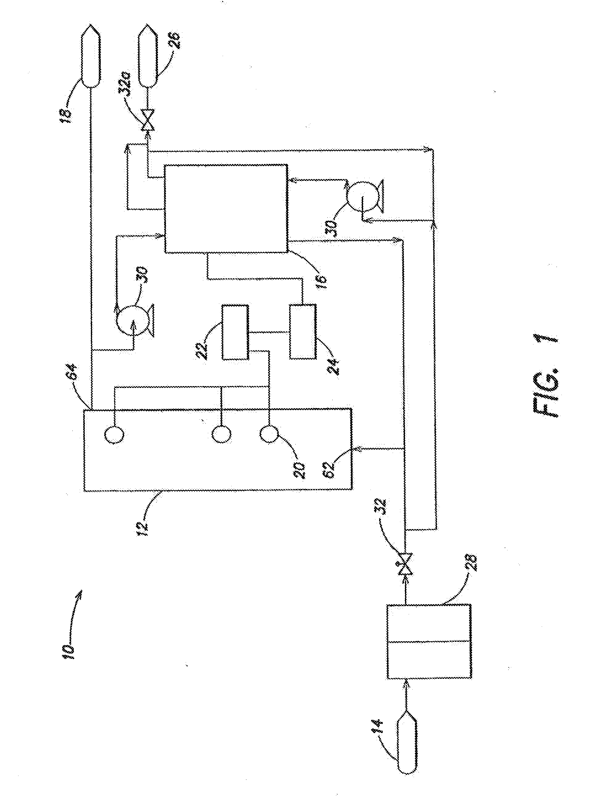
[0220]An in-line pressurized water treatment system in accordance with one or more embodiments of the systems and techniques of the present invention, schematically shown in FIG. 3, was evaluated for performance. The water treatment system 10 had an electrodeionization module 16 with a pretreatment system (not shown) and a pressurized storage vessel 12. Water, from point of entry 14, was introduced into pressurized vessel 12 and was circulated through electrodeionization module 16. The water treatment system was controlled by a programmable controller (not shown) based on a measured water conductivity, as measured by sensors 20b and 20c, upstream of an inlet 62 and downstream of an outlet 64 of pressurized vessel 12.

[0221]Electrodeionization device 16 comprised of a 10-cell pair stack with 13 inch flow paths. Each cell was filled with about 40% AMBERLITE® SF 120 resin and about 60% AMBERLITE® IRA 458 resin, both available from Rohm & Haas Company, Philadelphia, Pa. The electrodeioni...

example 2

[0227]An in-line pressurized water treatment system in accordance with one or more embodiments of the present invention, schematically shown in FIG. 5, was evaluated for performance. The water treatment system 10 had an electrodeionization module 16 and a pressurized storage vessel 12. Water, from point of entry 14, was introduced into pressurized storage vessel 12 through inlet 62, circulated using pumps 30a and 30b, and treated through pretreatment units 28a and 28b and electrodeionization module 16. The water treatment system was controlled by a programmable controller (not shown) based on the measured water conductivity, as measured by sensors any of 20a, 20b, and 20c.

[0228]Electrodeionization device 16 comprised of a 10-cell pair stack with flow paths that were about 7.5 inches long and about 2.5 inches wide. Each cell was filled with about 40% AMBERLITE® SF 120 resin and about 60% AMBERLITE® IRA 458 resin, both available from Rohm & Haas Company, Philadelphia, Pa. The electro...

example 3

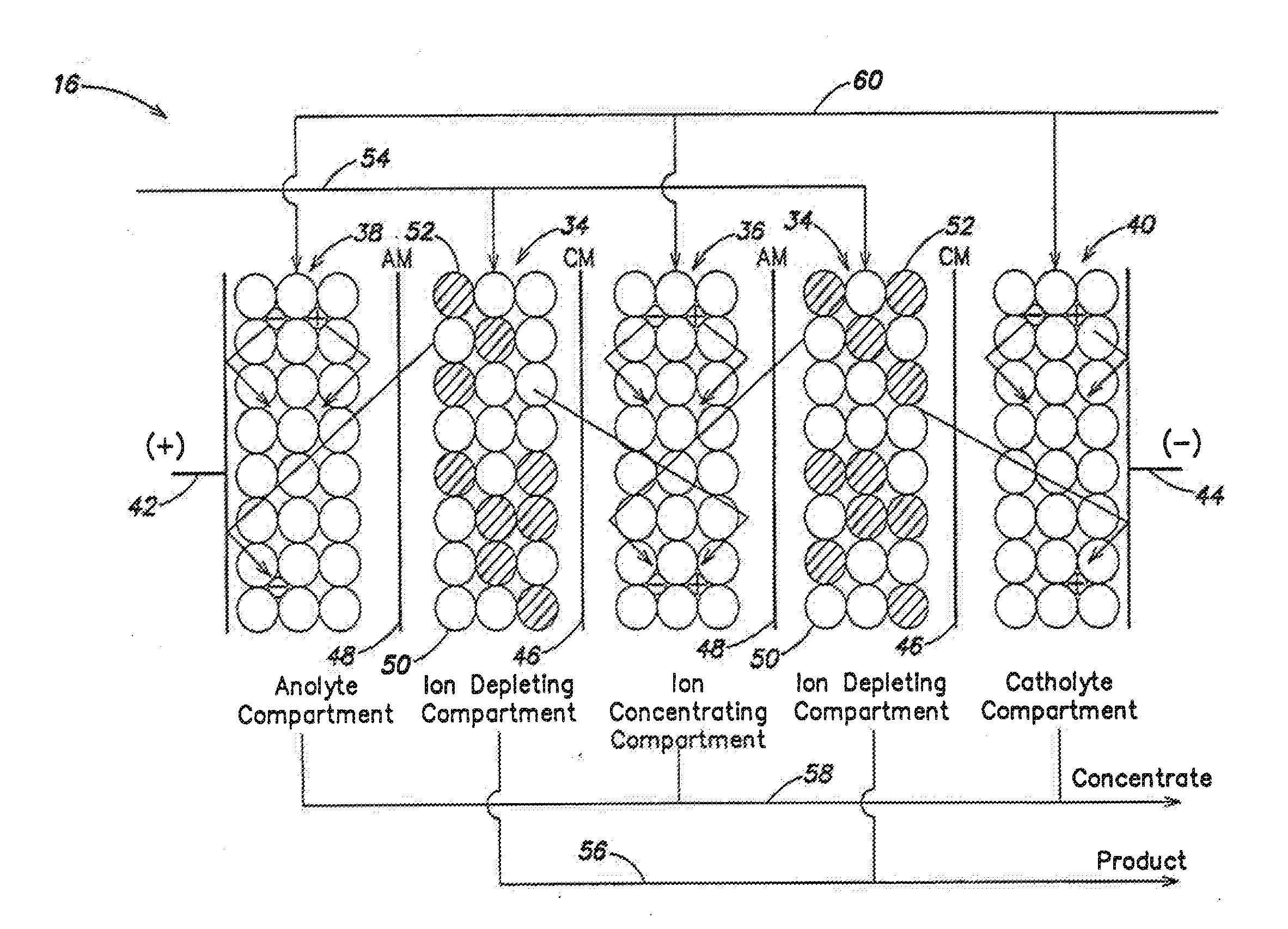
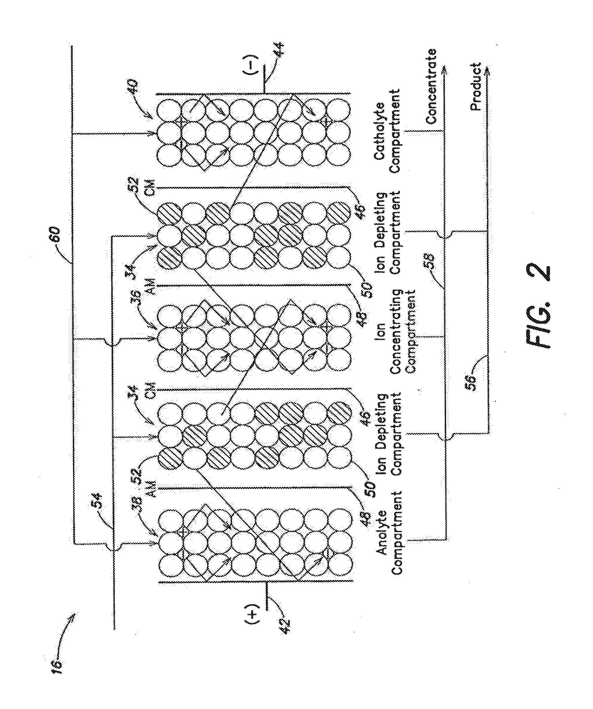
[0235]This example demonstrates an electrodeionization device that can generate and accumulated hydrogen ions in a compartment. A section of the electrodeionization device used in this example is schematically illustrated in FIG. 12. The electrodeionization device 16 had five cell pairs totaling ten compartments between the electrode compartments 38 and 40. Cathode compartment 38 was bounded by a cation-selective membrane 46. An adjacent compartment, concentrating compartment 36, was filled with a mixture of cation-exchanged resin 50 and anion-exchange resin 52. Specifically, the electroactive media was a mixed bed of about 60% AMBERLITE® IRA 458 and about 40% AMBERLITE® SF 120 resin, both available from Rohm & Haas Company, Philadelphia, Pa. Concentrating compartment 36, immediately adjacent to cathode compartment 38, was bounded by cation-selective membrane 46 and an anion-selective membrane 48 opposite the cation-selective membrane. Immediately adjacent to concentrating compartme...


PUM

PropertyMeasurementUnit
differential pressureaaaaaaaaaa
conductivityaaaaaaaaaa

Abstract

A water treatment system provides treated water to a point of use by removing at least a portion of any hardness-causing species contained in water from a water source, such as municipal water, well water, brackish water and water containing foulants. The water treatment system typically receives water from the water source or a point of entry and purifies the water containing at least some undesirable species before delivering the treated water to a point of use. The water treatment system has a pressurized reservoir system in line with an electrochemical device such as an electrodeionization device. The water treatment system can have a controller for adjusting or regulating at least one operating parameter of the treatment system or a component of the water treatment system. The electrochemical device can be operated at a low current and low flow rate to minimize water splitting or polarization, which minimizes scale formation.

Description

CROSS-REFERENCE TO RELATED APPLICATIONS[0001]This application is a continuation application of co-pending U.S. patent application Ser. No. 10 / 712,621; titled WATER TREATMENT SYSTEM AND METHOD, filed on Nov. 13, 2003; this application is also a continuation application of co-pending U.S. patent application Ser. No. 11 / 311,528, titled WATER TREATMENT SYSTEM AND METHOD, filed on Dec. 19, 2005, which is a divisional application of U.S. patent application Ser. No. 10 / 712,248, titled WATER TREATMENT SYSTEM AND METHOD, filed on Nov. 13, 2003, and granted as U.S. Pat. No. 7,083,733; this application is also a continuation application of co-pending U.S. patent application Ser. No. 12 / 477,013, titled WATER TREATMENT SYSTEM AND METHOD, filed on Jun. 2, 2009, which is a divisional application of U.S. patent application Ser. No. 10 / 712,163, titled WATER TREATMENT SYSTEM AND METHOD, filed on Nov. 13, 2003, and granted as U.S. Pat. No. 7,563,351; this application is also a continuation application...

Claims


Application Information

Patent Timeline
Patent Type & Authority Applications(United States)
IPC IPC(8): C02F1/461C25B9/00B01D61/48C02F1/00C02F1/28C02F1/44C02F1/46C02F5/00
CPCB01D61/48C02F1/283C02F1/441C02F1/46C02F5/00C02F2209/00C02F2301/066C02F2209/02C02F2209/03C02F2209/05C02F2209/06C02F2209/11C02F2209/40C02F2209/006
Inventor JHA, ANIL D.WILKINS, FREDERICKFREYDINA, EVGENIYASEZGI, AYTACMADHUSUDAN, RESHMAREARDON, MICHAEL
Owner EVOQUA WATER TECH LLC
Why Eureka
Try Eureka