Method of manufacturing a composite element

a manufacturing method and composite element technology, applied in dough shaping, applications, other domestic articles, etc., can solve the problems of laborious and time-consuming manual lay-up process, only able to build a relatively simple structure,

Inactive Publication Date: 2011-05-26
AIRBUS OPERATIONS LTD
View PDF15 Cites 17 Cited by
  • Summary
  • Abstract
  • Description
  • Claims
  • Application Information

AI Technical Summary

Benefits of technology

[0017]Preferably the method comprises placing an additional component between two or more cassette parts to form a cassette; inserting the cassette into a recess in one of the tools; injecting a liquid matrix material into the additional component in the recess; and curing the liquid matrix material in the additional component. In the embodiments described below the composite element is an aircraft spar and the additional components are rib posts. However the method may b

Problems solved by technology

Also, the ATL process is only able to build a relatively simple structure with small thickness variations, simple pad-ups and

Method used


Image

  • Method of manufacturing a composite element
  • Method of manufacturing a composite element
  • Method of manufacturing a composite element

Examples


Embodiment Construction

)

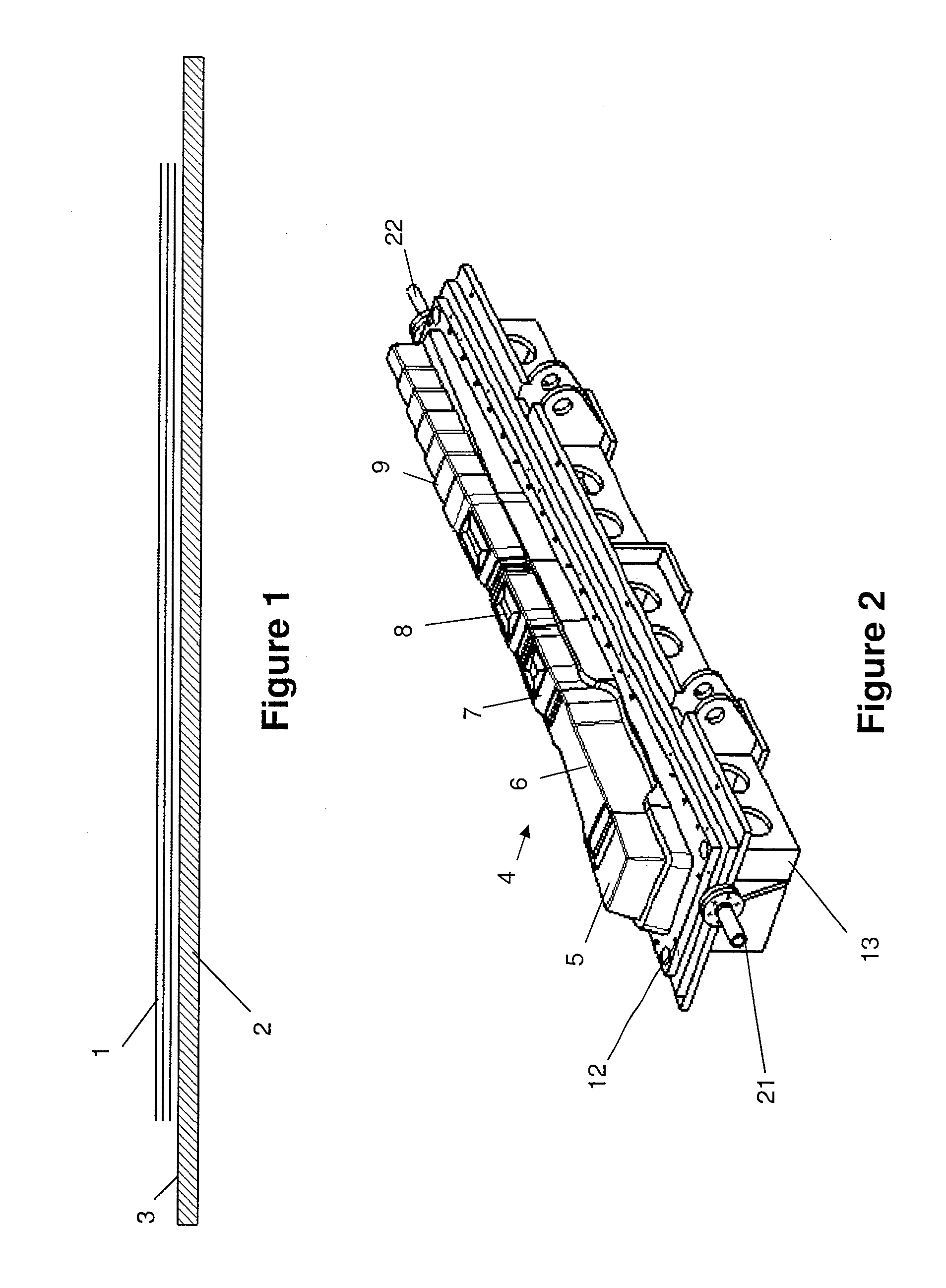
[0052]A method of manufacturing a composite rear spar is shown in FIGS. 1 to 22. In a first step shown in FIG. 1, a stack 1 of dry-fibre plies is assembled on a lay-up table 2. Each ply comprises a 12K High Tensile Strength (HTS) Advanced Unidirectional Weave (AUW) 285 g / m2 with EPR05311 binder. More specifically, each ply comprises a layer of carbon fibres extending in one direction, woven in a weaving loom with glass fibres extending at right angles to the carbon fibres. EPR05311 is provided as a powdered material by Hexion Specialty Chemicals. The powder is applied to the top of the weave and melted with an infrared lamp to form small droplets.

[0053]The stack is assembled manually ply by ply with assistance from a laser projector. Another option would be using robots with vacuum grippers to pick up the plies from a cutter and lay them up. The periphery of each individual ply is cut into a desired shape by an ultrasonic knife before the ply is laid onto the lay-up table. Location...


PUM

PropertyMeasurementUnit
Forceaaaaaaaaaa
Pressureaaaaaaaaaa
Melting pointaaaaaaaaaa

Abstract

A method of manufacturing a composite element. A stack of plies is assembled on a lay-up table, each ply comprising a plurality of reinforcement elements such as dry-fibres. A first part of the stack of plies is bound to form a partially bound stack of plies, a second part of the stack of plies remaining unbound. The partially bound stack of plies is press-formed in a mould cavity between a pair of mould tools to form a shaped pre-form, plies in the second part of the stack sliding against each other during the press-forming. A liquid matrix material is injected into the shaped pre-form in the mould cavity and subsequently cured.

Description

FIELD OF THE INVENTION[0001]The present invention relates to a method of manufacturing a composite element.BACKGROUND OF THE INVENTION[0002]Current state of the art composite large aircraft wing spars are typically manufactured from prepreg materials with Automated Tape Laying (ATL) and then hot formed to the desired shape over a male mandrel. The spar is then cured either on a male tool or in a female tool. Prepreg manufacture requires the use of an autoclave, which is a large capital investment. Also, the ATL process is only able to build a relatively simple structure with small thickness variations, simple pad-ups and shallow ramps, and any folding lines being more or less straight. More complex geometries and fibre architectures require the prepreg to be laid manually or with the use of fibre placement.[0003]An alternative process for manufacturing a composite component is so-called Resin Transfer Moulding (RTM) in which dry fibre is infused with liquid resin between a rigid mal...

Claims


Application Information

Patent Timeline
IPC IPC(8): B29C70/48
CPCB29B11/16B29L2031/003B29C70/543B29C70/48B29L2031/3085B29C70/54B29C33/306
Inventor TOPPING, SIMON W.EDWARDS, MARTINKALLINEN, RISTOHAACK, NILS
Owner AIRBUS OPERATIONS LTD
Why Eureka
Try Eureka