Wireless transmitter-receiver and mobile object management system

a wireless transmitter and receiver technology, applied in the direction of location information based service, wireless commuication service, machine-to-machine/machine-type communication service, etc., can solve the problems of increasing the demand for humidity/temperature management etc. of food during transportation, inability to use inside a building, and difficulty for a single industry association or a personal user to install an infrastructure of wireless media, etc., to achieve low cost and time, and low power dissip

Inactive Publication Date: 2011-05-26
HITACHI PLANT TECH LTD
View PDF14 Cites 58 Cited by
  • Summary
  • Abstract
  • Description
  • Claims
  • Application Information

AI Technical Summary

Benefits of technology

[0044]As stated above, by utilizing a wireless transmitting and receiving terminal including a location information acquiring unit, a clock information acquisition unit, a clock function unit for storing a clock information, and a data storing means, which is driven by a battery with low power dissipation, and also utilizing a wireless LAN which is available as a standard worldwide with wireless media of a wireless sensor network, it becomes possible to monitor a measured object referring to a status with time and location information with low cost and time.

Problems solved by technology

It is difficult for a single industry association or a personal user to install an infrastructure of wireless media for supporting wireless communication between the long distance wireless communication transmitting terminals above.
In recent years, problems that are related to securing food safety are closed up, and therefore a demand for humidity / temperature management etc. of the food during transport is increasing.
Since a GPS system uses satellite communications, which cannot be used inside a building.
Therefore, it is difficult to obtain accurate information like room location in a building.
In a case a travel distance is large when a mobile object travels between buildings being far apart, it is difficult to build up an infrastructure of long distance wireless communications covering the whole area by using a sensor network system based on the above mentioned near field wireless communication.
In addition, extra work is required such as transmitting the sensor data to a data server, or displaying the data on a SCADA (supervisory control and data acquisition system) and so forth, which results in increase of working hours and employment cost.
However, although labor cost is not necessary as the information is automatically transmitted, huge communication charge may be required depending on the system size.
Due to this reason, the location information can be acquired when traveling outdoor, but detailed information like specifying a room when traveling in a building cannot be obtained.
However, in an example of JP2005-71295, a mobile object is limited to a track.
Further, the mobile object is limited to a container which is carried on the track, and a sensor station is driven by a power source of the track.
Therefore, the sensor information cannot be transmitted if the measured object (container) is unloaded from the track.
So, it is required to collect the information by other means after the measured object (container) is unloaded or when traveling in a building during or after the transportation, which makes the seamless data collection difficult.
Accordingly, time and money may be wasted in the long run.
Due to this reason, the location information can be acquired when traveling outdoor, but detailed information like room location when traveling in a building cannot be obtained.

Method used


Image

  • Wireless transmitter-receiver and mobile object management system
  • Wireless transmitter-receiver and mobile object management system
  • Wireless transmitter-receiver and mobile object management system

Examples


embodiment 1

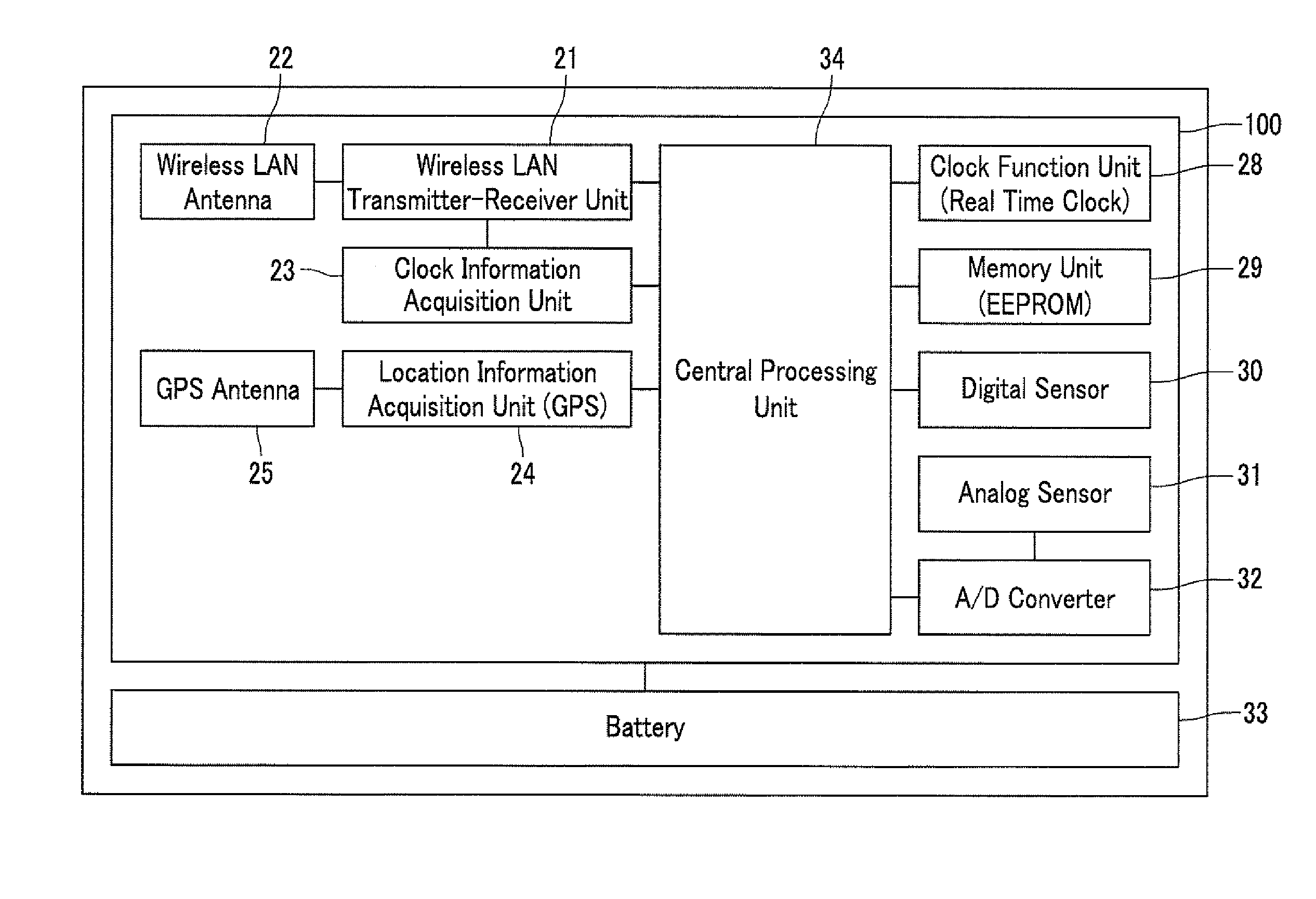
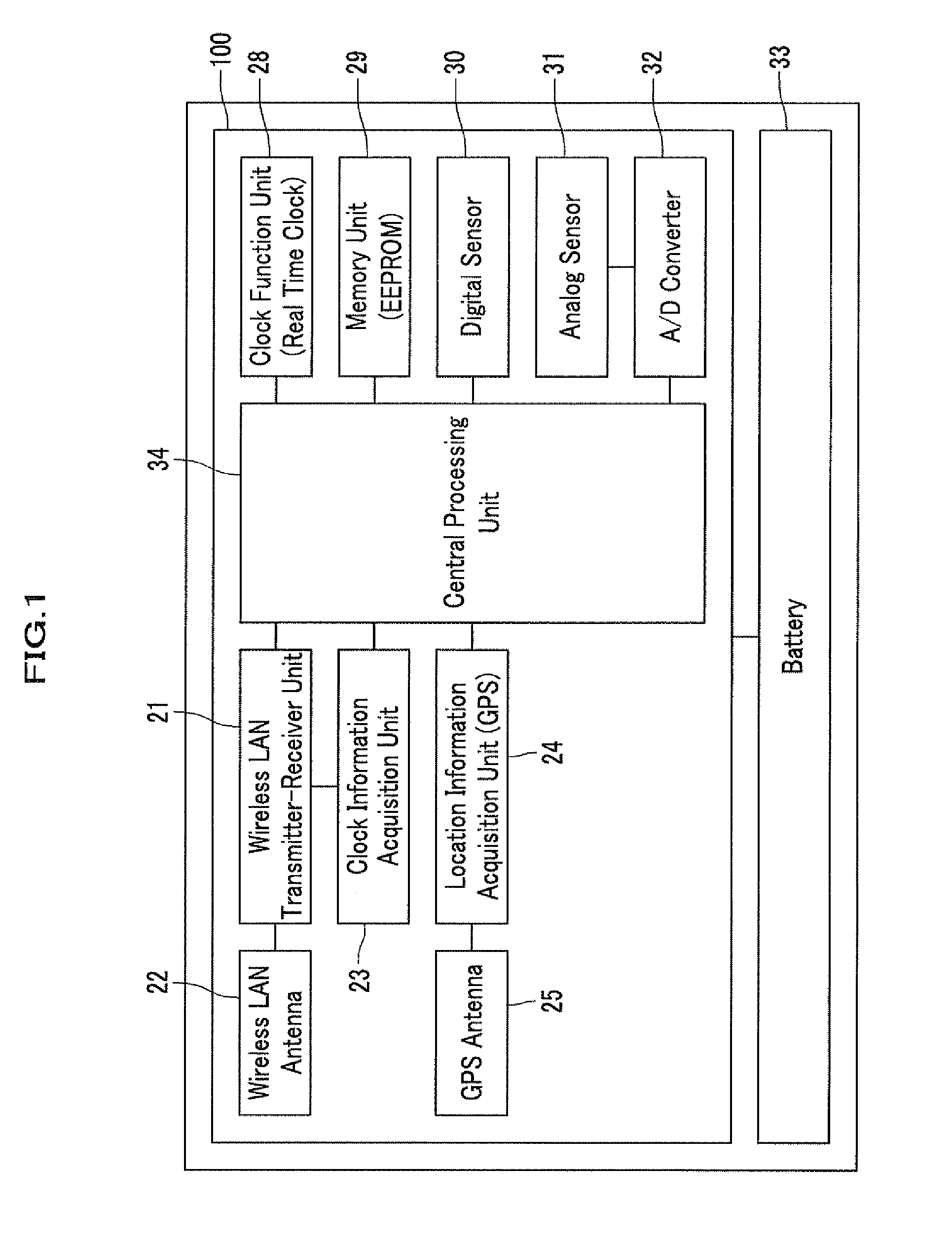
[0057]Embodiment 1 of the present invention is a wireless transmitter-receiver including: a sensor that acquires one or more pieces of information; a location information acquisition unit; a clock information acquisition unit; a clock function unit that stores the clock information; a memory unit for storing data; a wireless LAN transmitter-receiver unit; and a central processing unit that controls each unit; wherein the wireless transmitter-receiver periodically and wirelessly transmits the sensor information, the location information, and the clock information within a coverage area of a wireless LAN access point.

[0058]A structure of a wireless transmitter-receiver in accordance with Embodiment 1 of the present invention will be explained by referring to FIG. 1. FIG. 1 shows a block diagram of a wireless transmitter-receiver in accordance with an embodiment of the present invention. A numeric character 20 denotes a wireless transmitter-receiver according to the present invention, ...

embodiment 2

[0114]In a wireless transmitter-receiver of Embodiment 2 according to the present invention, a memory unit is a rewritable and erasable nonvolatile memory such as an EEPROM. Sensor information, location information, and clock information are stored in the memory unit when wireless communication is not available. Upon a wireless LAN access point becoming accessible, the stored sensor information, location information, and clock information are transmitted altogether, which allows acquiring various types of information acquired while the wireless transmitter-receiver is outside the coverage area of a wireless LAN access point.

[0115]That is, in Embodiment 2, a rewritable and erasable nonvolatile memory such as an EEPROM is used as the memory unit 29 explained in the embodiment in FIG. 1.

[0116]Sensor information, location information, and clock information are stored in the memory unit 29 when wireless communication is not available. Upon a wireless LAN access point becoming accessible,...

embodiment 3

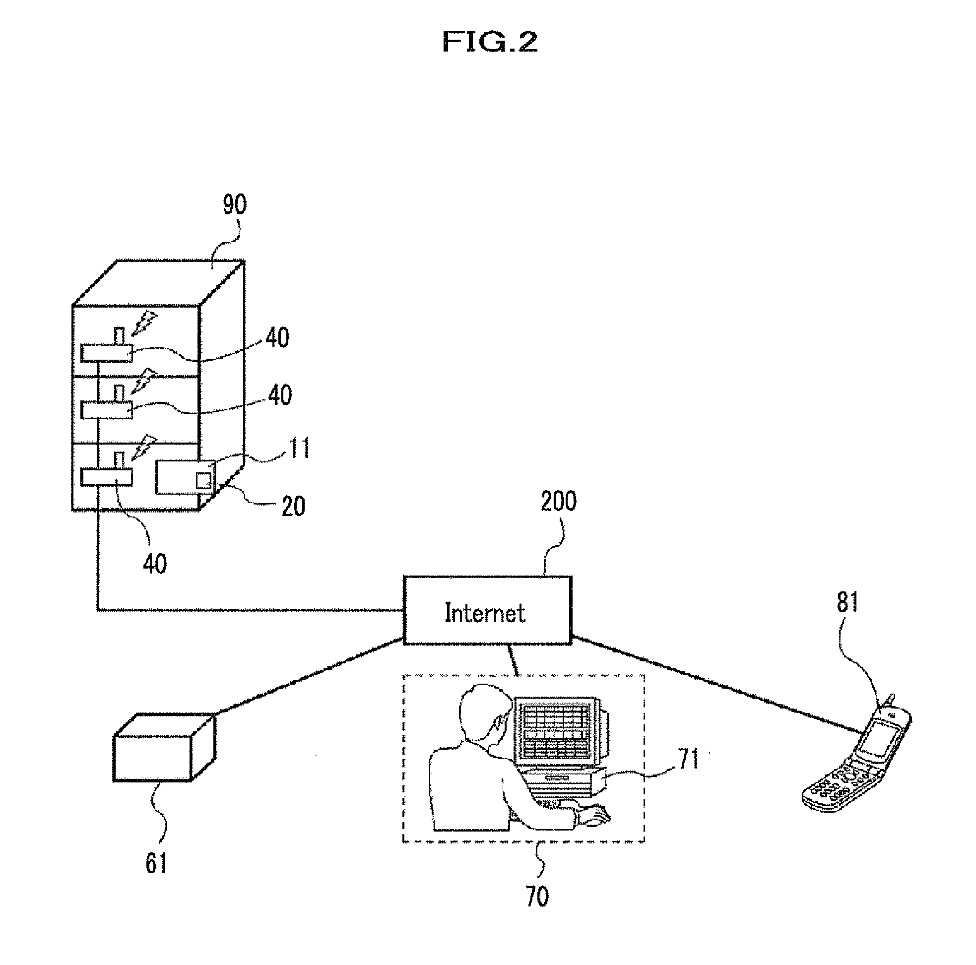
[0136]In a wireless transmitter-receiver of Embodiment 3 according to the present invention, GPS is used for the location information acquisition unit. Inside the coverage area of a wireless LAN access point, the wireless transmitter-receiver does not acquire location information from the GPS but scans a signal periodically sent from wireless LAN access points, performs authentication and connection with a wireless LAN access point that has the highest field intensity, and acquires wireless LAN access point information. Then the wireless transmitter-receiver packetizes the information and sends the packet to a data server. The data server associates the wireless LAN access point information and location information of the wireless LAN access point in advance. By so doing, more detailed location information can be obtained in addition to the location information from the GPS.

[0137]Meanwhile, when the wireless transmitter-receiver is outside the coverage area of the wireless LAN acces...


PUM


Abstract

A concise and low cost mobile object management system which is capable of monitoring a state of a mobile object via a wireless transmitter-receiver having a wireless LAN function is provided. The mobile object management system includes a sensor for acquiring various information of a mobile object, a clock information acquisition unit, a memory unit for storing data, and a wireless LAN transmitter-receiver unit, each controlled by a Central Processing Unit, and transmits wirelessly a state of a measured object on the mobile object, location information, and clock information. By adopting a wireless LAN for the wireless transmitting and receiving function, it is possible to implement a concise and low cost system which is highly versatile and capable of utilizing a most common infrastructure.

Description

CROSS REFERENCE TO RELATED APPLICATION[0001]The present application claims benefit of the filing dates of Japanese Patent Application No. 2009-260637 filed on Nov. 16, 2009, which is incorporated herein by reference.BACKGROUND OF THE INVENTION[0002]1. Field of the Invention[0003]The present invention relates to a wireless transmitter-receiver that transmits and receives status and location information of a mobile object via a wireless LAN (Local Area Network), and to a mobile object management system.[0004]2. Description of the Related Art[0005]In recent years, a wireless sensor network system gathers attention as a fundamental technology of a new network system for transmitting various types of information. A wireless sensor network system includes, a wireless terminal equipped with sensors for sensing humidity / temperature, pressure, oscillation, sound, location, and other information, and a wireless transmitting and receiving means for the sensed information. In other words, a sen...

Claims


Application Information

Patent Timeline
Patent Type & Authority Applications(United States)
IPC IPC(8): H04W84/02H04W4/02H04W4/029H04W4/70
CPCH04W4/005H04W4/02H04W64/00H04L67/2842H04L67/2861H04L67/12H04W84/12H04W4/70H04W4/029H04L67/568H04L67/59
Inventor YASHIRO, YUICHIITO, TSUTOMUAKI, TAKAFUMI
Owner HITACHI PLANT TECH LTD
Why Eureka
Try Eureka