Fuel supply system having pressure control valve

Inactive Publication Date: 2011-05-26
DENSO CORP
View PDF5 Cites 43 Cited by
  • Summary
  • Abstract
  • Description
  • Claims
  • Application Information

AI Technical Summary

Benefits of technology

[0040]Since the fuel pressure in the fuel delivery pipe is increased by stopping the fuel injection from the fuel injection device into the cylinder, it is possible to rapidly increase the fuel pressure in the fuel delivery pipe above the first pressure.
[0041]When the pressure relief valve is opened, the fuel pressure in the fuel delivery pipe is decreased. As a result, atomization of the

Problems solved by technology

(1) A problem, which may occur in the case that the fuel pressure is maintained at the constant high value in the fuel delivery pipe when releasing the acceleration pedal:
If the fuel pressure in the fuel delivery pipe was maintained at the high pressure during such a case (pressure release of the acceleration pedal), it may become difficult to smoothly control amount of fuel injection from the fuel injection devices into the combustion chambers when the acceleration pedal is pressed again.
As a result, fuel consumption ratio may be decreased, a shock may be generated during a vehicle accelerating operation, and so on.
(2) A problem, which may be caused by fuel pressure increase in the fuel delivery pipe after stopping the engine operation:
When the fuel pressure is increased in the fuel delivery pipe, the fuel may leak from the fuel injection devices into the combustion chambers.
The fuel leaked into the combustion chambers may be emitted into the air as unburned components at starting the engine next time, which may deteriorate emission.
Therefore, a lifting amount of the valve body when opening the fuel line is small.
Accordingly, when the engine i

Method used


Image

  • Fuel supply system having pressure control valve
  • Fuel supply system having pressure control valve
  • Fuel supply system having pressure control valve

Examples


first embodiment

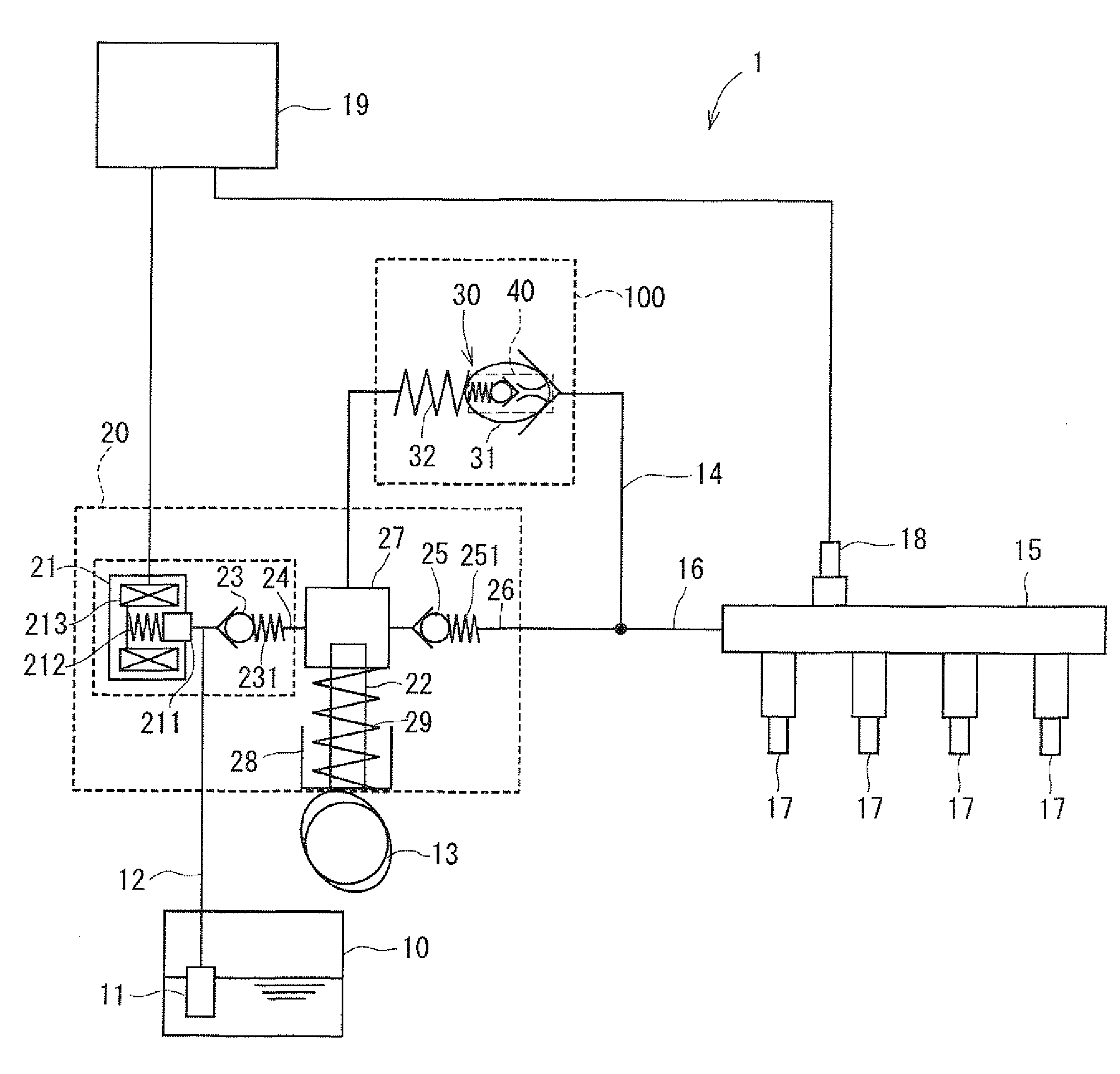
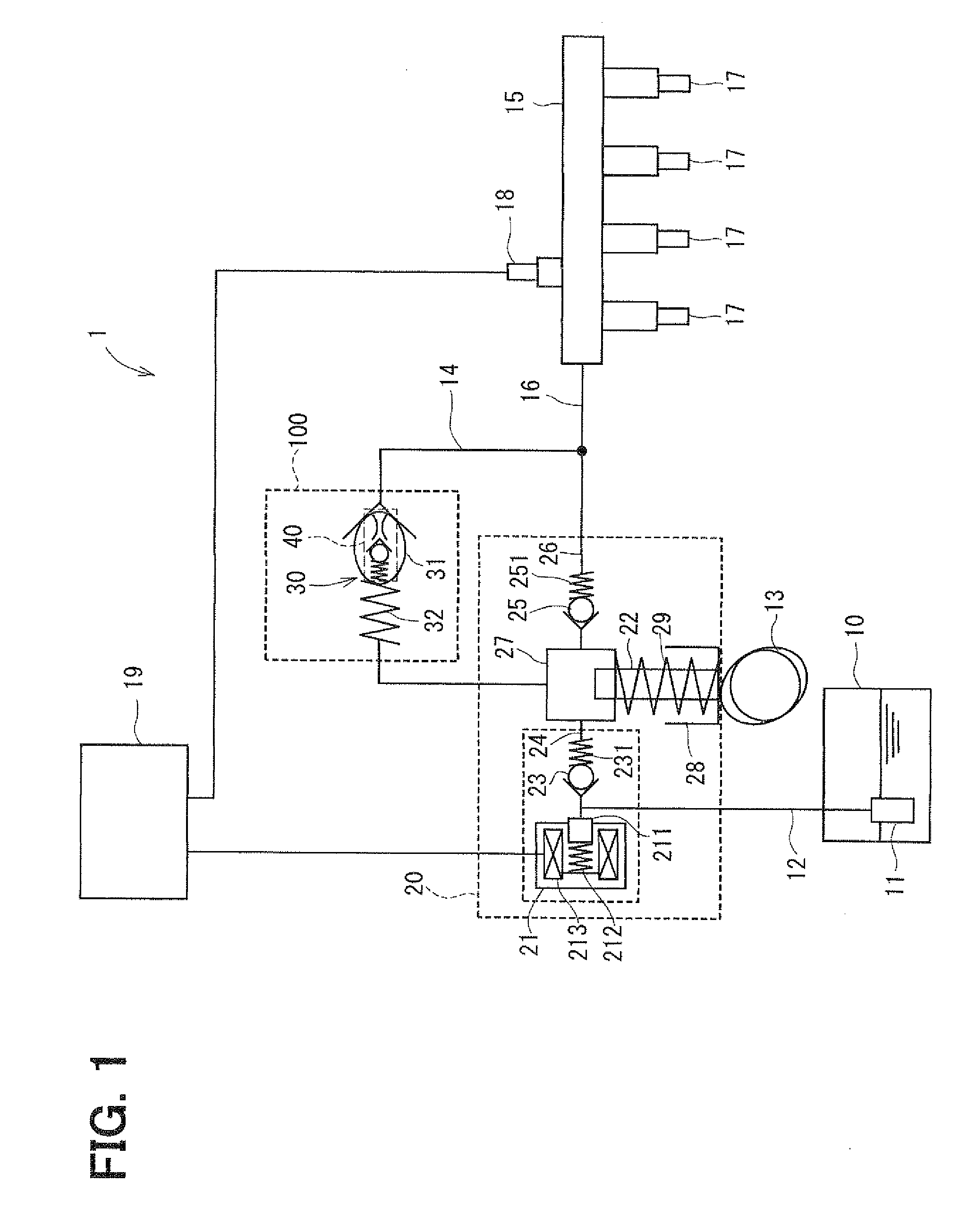
[0071]A fuel supply system, to which a pressure control valve according to a first embodiment of the present invention is applied, is a fuel supply system 1 for an internal combustion engine of a direct-injection type, in which fuel is directly injected into cylinders (combustion chambers) the engine. As shown in FIG. 1, the fuel supply system 1 is composed of a fuel tank 10, a high pressure pump 20, a fuel delivery pipe 15, fuel injection devices (injectors) 17, a pressure relief valve 30, a pressure holding valve 40 (also referred to as a constant residual pressure valve), a fuel pressure sensor 18, a controller (an electronic control unit) 19, and so on. A pressure control valve 100 is composed of the pressure relief valve 30, the pressure holding valve 40 and so on.

[0072]Fuel is drawn up by a low pressure fuel pump 11 from the fuel tank 10 and supplied to the high pressure fuel pump 20 via a low pressure fuel pipe 12. The fuel is pressurized by the high pressure fuel pump 20 and...

second embodiment

[0145]A fuel supply system, to which a pressure control valve according to a second embodiment of the invention is applied, will be explained with reference to FIGS. 10A and 10B.

[0146]According to the second embodiment, when the controller 19 determines at the step 54 (FIG. 10B) that the flag for the abnormal condition stored in the memory is “1”, YES at the step S4, the process is continued until the fuel pressure in the fuel delivery pipe 15 becomes higher than a predetermined value (NO at the step S6, FIG. 10B), and then the process is changed to the cleaning mode operation when the fuel pressure in the fuel delivery pipe 15 becomes higher than the predetermined value (YES at the step S6, FIG. 105).

[0147]The predetermined value means here pressure, which is close to but lower than the first pressure. Furthermore, the predetermined value means pressure in the fuel delivery pipe 15, which is close to maximum fuel injection pressure for the injections 17 during the vehicle accelerat...

third embodiment

[0149]A pressure control valve according to a third embodiment of the invention will be explained with reference to FIG. 11. Shapes of a stopper 50 and a first spring 55 of the pressure relief valve 30 according to the third embodiment are different from those of the first embodiment.

[0150]The stopper 50 is formed in a cylindrical shape having a large diameter portion 51 and a small diameter portion 52. An outer peripheral wall of the large diameter portion 51 is fixed to the inner peripheral wall of the fuel return pipe 14. The small diameter portion 52 extends from one end of the large diameter portion 51 in the direction to the fuel delivery pipe 15.

[0151]A first through-hole 53 is formed in the stopper 50, which extends in its axial direction so that both axial end spaces thereof are communicated with each other. A second through-hole 54 is formed in the small diameter portion 52, wherein the second through-hole 54 extends in a radial direction. The first and second through-hole...


PUM


Abstract

A pressure control valve is provided in a fuel return pipe connected between a high pressure fuel pipe and a fuel pressurizing chamber of a high pressure pump. A pressure relief valve is opened when fuel pressure in a fuel delivery pipe is higher than a first pressure. A first valve body of the pressure relief valve is brought into contact with a stopper so that a movement of the first valve body is limited. A pressure holding valve, which is provided in an inside of the first valve body, is opened when the fuel pressure in the fuel delivery pipe is larger than a second pressure. When the pressure relief valve is opened and the first valve body crashes into the stopper, a lifting amount of a second valve body of the pressure holding valve is increased by inertia of the second valve body, so that extraneous material attached to the second valve body can be removed.

Description

CROSS REFERENCE TO RELATED APPLICATION[0001]This application is based on Japanese Patent Applications No. 2009-268971 filed on Nov. 26, 2009, and No. 2010-117173 filed on May 21, 2010, the disclosures of which are incorporated herein by reference.FIELD OF THE INVENTION[0002]The present invention relates to a fuel supply system for an internal combustion engine, in particular, relates to a pressure control valve provided in the fuel supply system.BACKGROUND OF THE INVENTION[0003]In a conventional fuel supply system for a direct injection type gasoline engine, a fuel from a fuel tank is pressurized by a high pressure pump and pressurized high fuel is supplied to and stored in a fuel delivery pipe, so that the high pressure fuel is injected into combustion chambers of the engine through fuel injection devices connected to the fuel delivery pipe.[0004]In the fuel supply system of this kind, a pressure relief valve is provided so as to decrease the fuel pressure in the fuel delivery pipe...

Claims


Application Information

Patent Timeline
IPC IPC(8): F02M37/04F02M55/02
CPCF02D41/126F02M2200/315F02D2041/224F02D2250/04F02M37/0023F02M59/366F02M59/46F02M59/466F02M63/005F02M63/0052F02M63/0056F02M63/0077F02M63/0245F02M63/028F02M2200/08F02D41/3863
Inventor SUZUKI, TAKASHIKOBAYASHI, MASAYUKIITOH, YOSHIHIKOOIKAWA, SHINOBUINOUE, HIROSHI
Owner DENSO CORP
Why Eureka
Try Eureka