Small antenna using srr structure in wireless communication system and method for manufacturing the same

Inactive Publication Date: 2011-06-02
ELECTRONICS & TELECOMM RES INST
View PDF5 Cites 21 Cited by
  • Summary
  • Abstract
  • Description
  • Claims
  • Application Information

AI Technical Summary

Benefits of technology

[0010]Another embodiment of the present invention is directed to a small antenna capable of easily controlling a frequency using an SRR structure in a wireless communication system and a method for manufacturing the same.
[0011]Another embodiment of the present invention is directed to a small antenna using an SRR structure in a wireless communication system, which does not require a match

Problems solved by technology

In general, however, since a small antenna has a large reactance component and a very small radiation resistance value, it is difficult to accomplish impedance matching.
Accordingly, since the small antenna has a very narrow impedance bandwidth and low efficiency, it exhibits a low gain characteristic.
This may increase the cost and time as well as the complexity when the small antenna is implemented.
Furthermore, when the additional matching network is provided for the impedance matching

Method used


Image

  • Small antenna using srr structure in wireless communication system and method for manufacturing the same
  • Small antenna using srr structure in wireless communication system and method for manufacturing the same
  • Small antenna using srr structure in wireless communication system and method for manufacturing the same

Examples


Example

[0021]Exemplary embodiments of the present invention will be described below in more detail with reference to the accompanying drawings. The present invention may, however, be embodied in different forms and should not be constructed as limited to the embodiments set forth herein. Rather, these embodiments are provided so that this disclosure will be thorough and complete, and will fully convey the scope of the present invention to those skilled in the art. Throughout the disclosure, like reference numerals refer to like parts throughout the various figures and embodiments of the present invention.

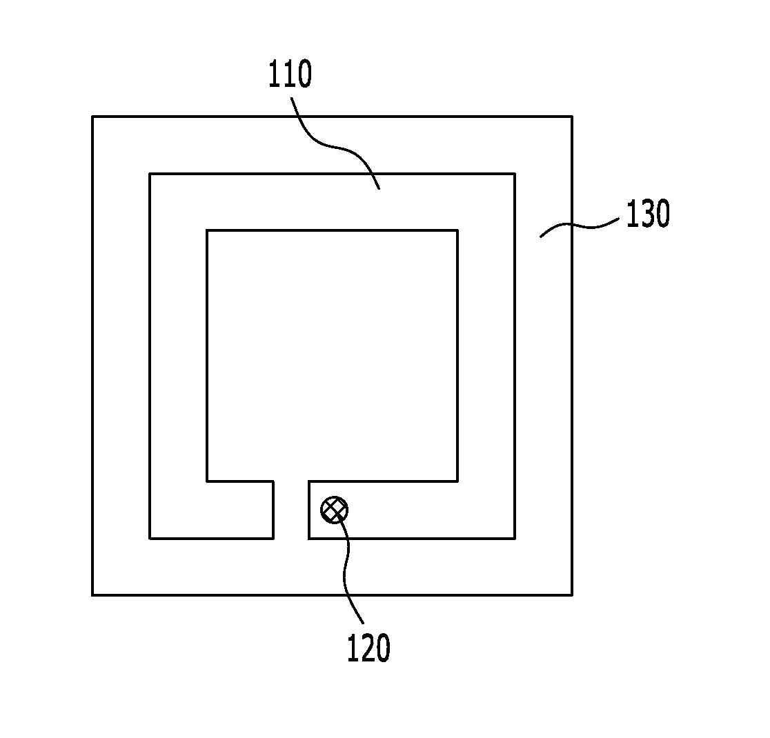
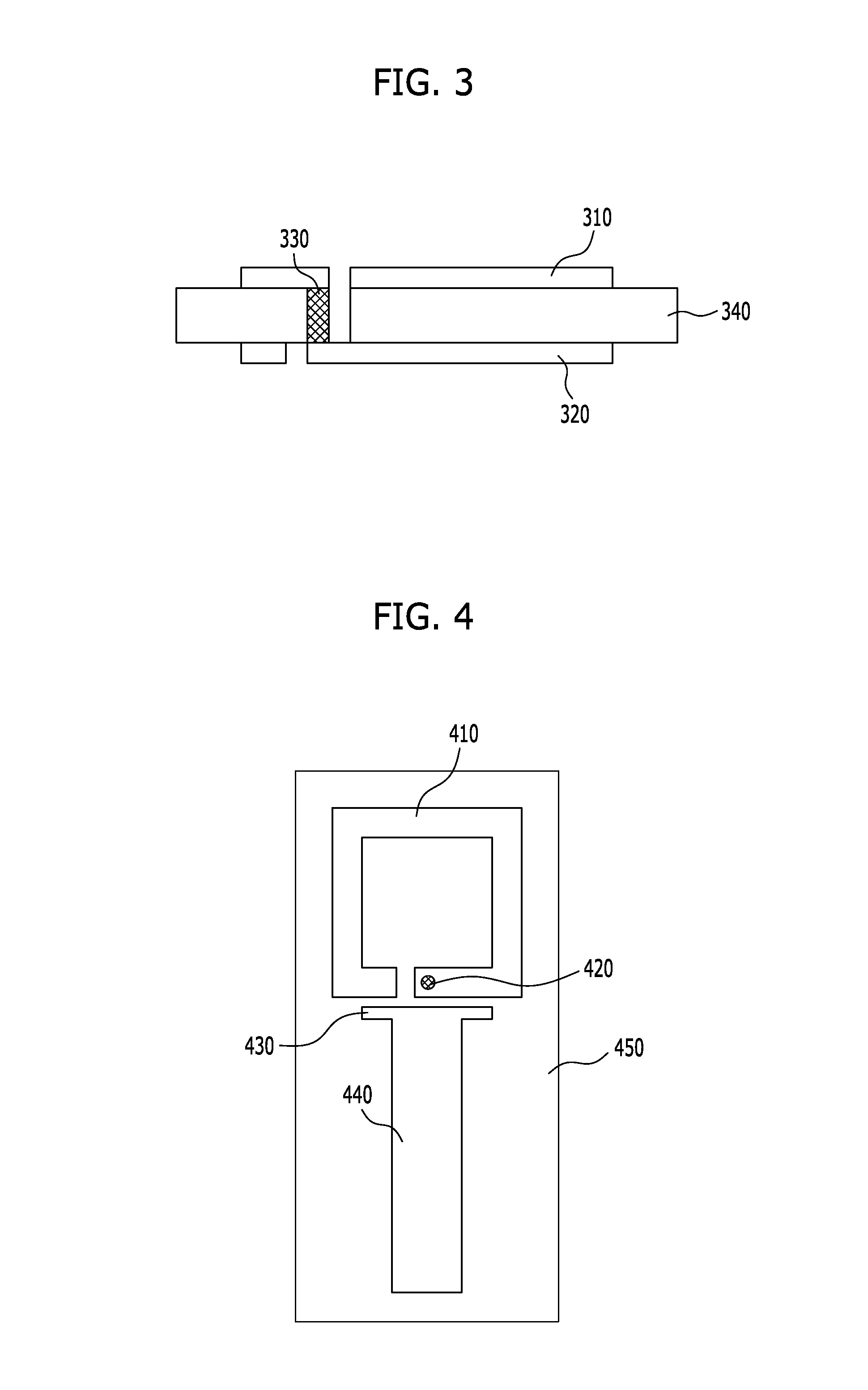
[0022]Exemplary embodiments of the present invention provide a small antenna capable of controlling a frequency in a wireless communication system and a method for manufacturing the same. In the embodiments of the present invention, an SRR structure is used to implement the small antenna. The small antenna implemented by using the SRR structure easily controls a resonant frequency without ...


PUM


Abstract

A small antenna using an SRR structure in a wireless communication system includes: a first radiation unit positioned over a dielectric substrate formed of a predetermined dielectric medium and having a predetermined ring shape; a feed unit positioned over the dielectric substrate and configured to feed a signal to the first radiation unit; a second radiation unit positioned under the dielectric substrate and having a predetermined ring shape; a via formed through the dielectric substrate to connect the first and second radiation units; a ground unit positioned under the dielectric substrate and configured to ground the first and second radiation units; and a metal line unit positioned under the dielectric substrate to connect the second radiation unit and the ground unit. The feed unit includes first and second capacitors which accomplish impedance matching when the signal is fed to the first radiation unit.

Description

CROSS-REFERENCE(S) TO RELATED APPLICATIONS[0001]The present application claims priority of Korean Patent Application No. 10-2009-0117393, filed on Nov. 30, 2009, which is incorporated herein by reference in its entirety.BACKGROUND OF THE INVENTION[0002]1. Field of the Invention[0003]Exemplary embodiments of the present invention relate to a wireless communication system; and, more particularly, to a small antenna which controls a resonant frequency using a split ring resonator (hereafter, referred to as SRR) structure in a wireless communication system, and a method for manufacturing the same.[0004]2. Description of Related Art[0005]In order to transmit and receive signals in a wireless communication system, various types of antennas have been proposed. The antennas are essential components in a wireless communication system for transmitting and receiving electromagnetic wave signals, and resonate at a specific frequency of electromagnetic wave to transmit and receive an electromagn...

Claims


Application Information

Patent Timeline
IPC IPC(8): H01Q1/38
CPCH01Q1/243H01Q9/42H01Q9/0407H01Q1/36H01Q1/38
Inventor JU, JEONGHOCHOI, JAE-ICKLEE, WANGJOOKIM, DONG-HO
Owner ELECTRONICS & TELECOMM RES INST
Why Eureka
Try Eureka