Dynamics-based motion generation apparatus and method

a technology of dynamic motion and motion control, applied in the field of computer graphics and robot control technology, can solve the problems of long time period, large amount of work, and difficulty in assigning the positions of the character skeleton, and achieve the effect of easy generation of robot motions

Inactive Publication Date: 2011-06-02
ELECTRONICS & TELECOMM RES INST
View PDF3 Cites 32 Cited by
  • Summary
  • Abstract
  • Description
  • Claims
  • Application Information

AI Technical Summary

Benefits of technology

[0023]The present invention provides a dynamics-based motion generation apparatus and method capable of correcting motion data created by an animator to objective motion data in compliance with the phy...

Problems solved by technology

However, since all the work is manually performed, a long period of time is required.
This structure makes the assignment of the positions of a character skeleton difficult.
The generation of the motions using this motion control method requires a large amount of work.
When the forward kinematics motion control method is used, work may be repeatedly performed because the location and orientation of an end node are not accurately predicted.
In contrast, if a 3D character represents a human or animal of a real-world, the generation of the motions of such a character is very difficult.
Therefore, it is very difficult to generate the real-world motions of a character using a kinematics motion control method.
That is, although it is not difficult to perform imitation similarly, detailed motion cannot be achieved only by the imagination without considering dynamics.
However, it is difficult to use a dynamics motion control method on the basis of only the skeleton of an existing character including the joints and bones.
Although an object can generally be moved freely with six degrees of freedom, the constrained object cannot be moved freely because of other forces (affects on it continuously).
Therefore, it is difficult to perform intuitive motion control using the dynamics method.
Meanwhile, since a skeleton is configured such that bon...

Method used


Image

  • Dynamics-based motion generation apparatus and method
  • Dynamics-based motion generation apparatus and method
  • Dynamics-based motion generation apparatus and method

Examples


Embodiment Construction

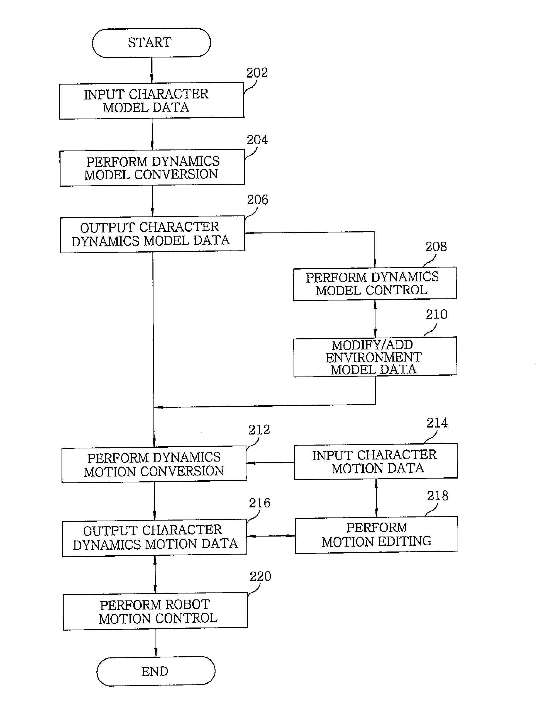
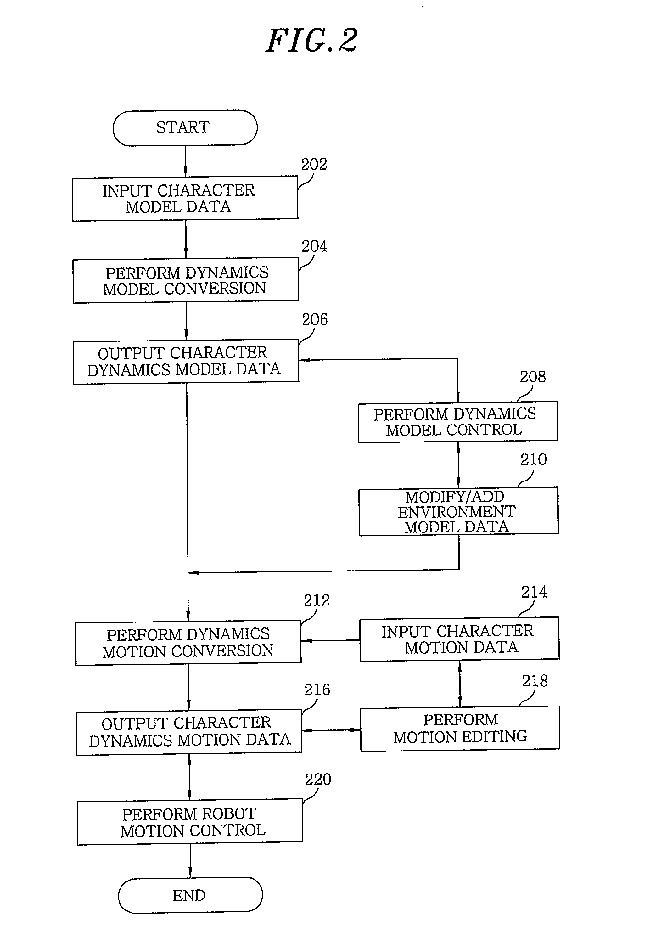
[0033]Hereinafter, dynamics-based motion generation apparatus and method in accordance with the embodiment of the present invention will be explained in detail with reference to the accompanying drawings which form a part hereof.

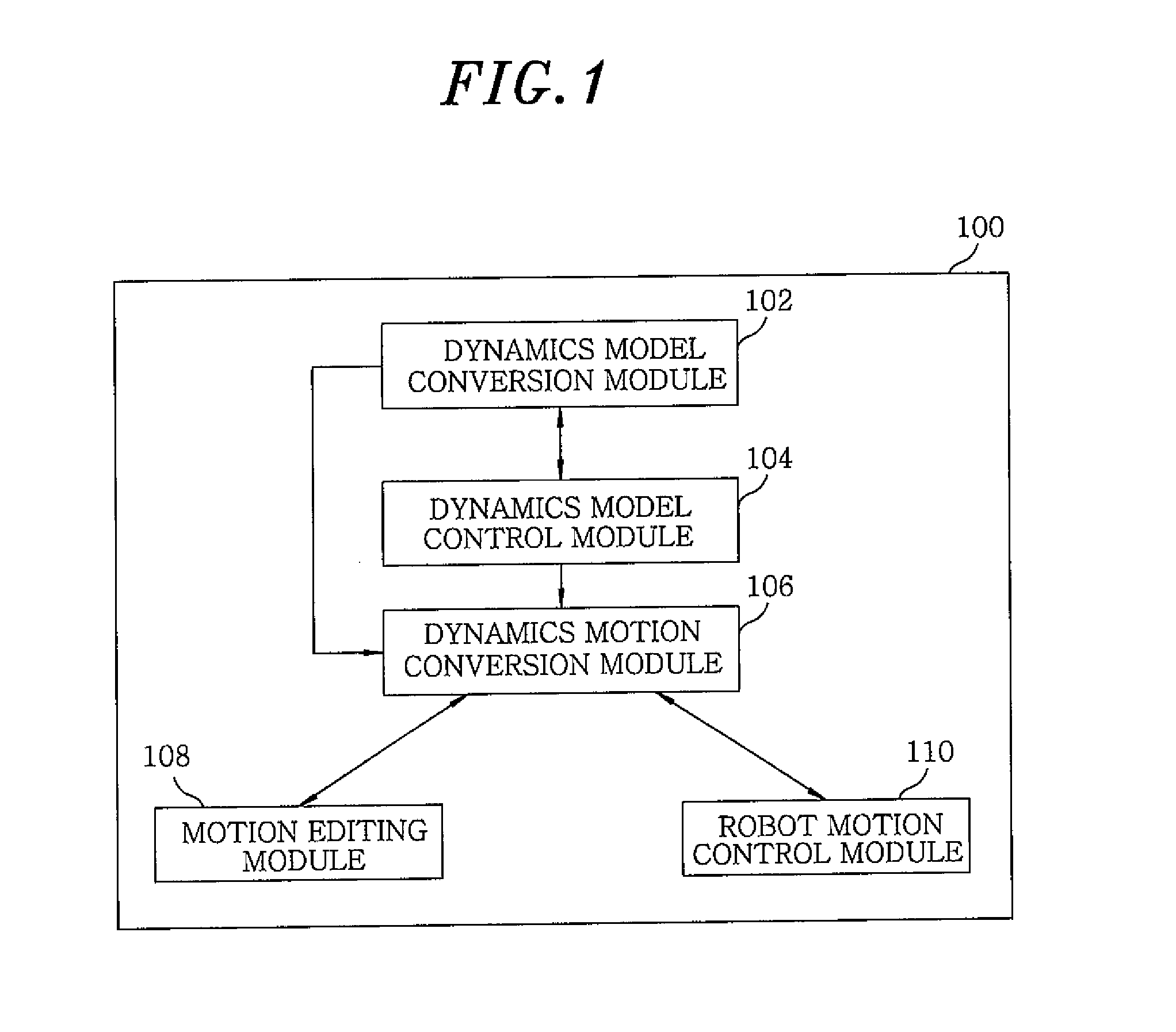
[0034]FIG. 1 is a block diagram showing a configuration of a dynamics-based motion generation apparatus 100 in accordance with the embodiment of the present invention.

[0035]Referring to FIG. 1, the dynamics-based motion generation apparatus 100 is provided on a computing device such as a computer, a notebook or a mobile phone to be used. The dynamics-based motion generation apparatus includes a dynamics model conversion module 102, a dynamics model control module 104, a dynamics motion conversion module 106, a motion editing module 108, and a robot motion control module 110.

[0036]In detail, the dynamics model conversion module 102 automatically converts model data including at least one of existing character skeleton data, skin mesh data and rigging data int...


PUM


Abstract

A dynamics-based motion generation apparatus includes: a dynamics model conversion unit for automatically converting character model data into dynamics model data of a character to be subjected to a dynamics simulation; a dynamics model control unit for modifying the dynamics model data and adding or modifying an environment model; a dynamics motion conversion unit for automatically converting reference motion data of the character, which has been created by using the character model data, into dynamics motion data through the dynamics simulation by referring to the dynamics model data and the environment model; and a motion editing unit for editing the reference motion data to decrease a gap between reference motion data and dynamics motion data. The apparatus further includes a robot motion control unit for controlling a robot by inputting preset torque values to related joint motors of the robot by referring to the dynamics motion data.

Description

CROSS-REFERENCE(S) TO RELATED APPLICATION[0001]The present invention claims priority of Korean Patent Application No. 10-2009-0118622, filed on Dec. 2, 2009, which is incorporated herein by reference.FIELD OF THE INVENTION[0002]The present invention relates to computer graphics and robot control technology, and, more particularly, to a dynamics-based motion generation apparatus and method which is adapted to provide a user interface capable of creating positions of a three-dimensional (3D) character model having joints corresponding with dynamic constraints and allowing the creation of motions to be easily implemented.BACKGROUND OF THE INVENTION[0003]In general, when a motion of a 3D character is created, the 3D character has a skeleton including joints and bones. The motion of a character is generated according to variations in the position of a character skeleton as time lapses. For example, when a 5-second's motion with 30 Hz frame rate is generated, a total of 150 (5*30) motion ...

Claims


Application Information

Patent Timeline
IPC IPC(8): G06T13/00
CPCG06T13/40G06T17/00
Inventor GHYME, SANG WONKIM, MYUNGGYUCHANG, SUNG JUNESUNG, MAN KYUJEONG, IL-KWONCHOI, BYOUNG TAE
Owner ELECTRONICS & TELECOMM RES INST
Why Eureka
Try Eureka