
Passive fluid flow regulator

a fluid flow regulator and passive technology, applied in the direction of flow monitors, wound drains, medical devices, etc., can solve the problems of complicated and expensive fabrication of such devices, affecting the flow of fluid through, so as to achieve easy and cheaper manufacturing and more flexibility.

Active Publication Date: 2011-06-09
DEBIOTECH SA
View PDF11 Cites 15 Cited by
  • Summary
  • Abstract
  • Description
  • Claims
  • Application Information

AI Technical Summary

Benefits of technology

[0016]Another aim of the present invention is to offset the drawback of the prior art mentioned above by proposing, as an alternative, a passive fluid flow regulator which is easier and cheaper to manufacture and which would provide more flexibility as far as its conditions of use are concerned.

Problems solved by technology

A known problem of these passive devices is that the drug flow rate to a delivery location, which may be a patient's body for instance, may vary as a function of the amount of drug remaining in the reservoir as far as the pressure in the reservoir depends on this amount.
As the membrane would come into contact with the substrate in the region of its central through hole, this would occlude the latter and result in hindering a fluid from flowing through it.
However, fabrication of such a device is complicated and expensive.
Indeed, the substrate has to be etched according to a specific pattern which is rather delicate regarding the accuracy level that has to be respected for the flow regulation to operate properly.
Thus, not only the manufacture of the substrate requires specific extra-steps, but these steps are further delicate to carry out.
Depending on the dimensions of the device, specific materials such as SOI is to be used for manufacture of the substrate, which is still more expensive.
Clinical experience has proven that this principle of shunting is not an ideal solution.
Sudden rises of the ICP, e.g. due to change of position, physical exercise, or pathological pressure waves result in excessive CSF drainage.
Several reports in the literature (Aschoff et al., 1995) point at problems due to this overdrainage, and especially the pronounced narrowing of the ventricles has been pointed out as being the main factor leading to malfunctioning of the implanted shunting device.
The reason is that the ventricular walls may collapse around the ventricular CSF shunt device, and particles (cells, debris) may intrude into the shunt device.
However, due to the elastomeric properties of the diaphragm material, maintenance of the implanted valve may be required.
Further, flow rate adjustment of this adjustable valve after implantation may require a surgical procedure.
Although the Watanabe device permits flow rate control palpably through the scalp and thus, without surgical intervention, patient and / or physician attention to the valve settings is required.
However, this device is intended for use with a shunt system including a valve for controlling flow rate and should be placed distal to the valve inducing cumbersome procedure due to the additional material to be implanted.

Method used


Image

  • Passive fluid flow regulator
  • Passive fluid flow regulator
  • Passive fluid flow regulator

Examples


Embodiment Construction

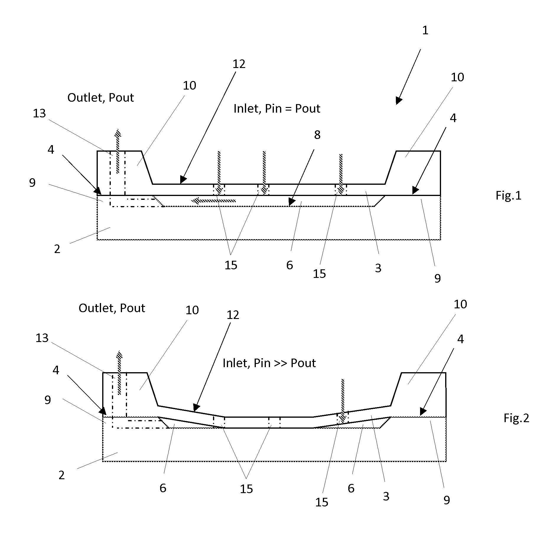
[0047]FIG. 1 and FIG. 2 show simplified cross-sectional views of a fluid flow regulator according to a first embodiment of the present invention the general behaviour of which, with respect to the pressure applied to it, is similar to that of the previously mentioned prior art device.

[0048]Indeed, the fluid flow regulator 1 shown on these drawings comprises a rigid substrate 2 and a resilient membrane 3 tightly linked together in predefined linking areas 4 so as to define a cavity 6 therebetween. The assembly of the membrane with the substrate may be carried out by direct or anodic bonding depending on the substrate material.

[0049]Typically, the linking areas 4 on both the substrate and the membrane may exhibit a roughness in the range between 0.5 and 100 nm RMS to avoid any leakage.

[0050]By way of a non-limiting example, the linking areas are located at the peripheries of both the substrate and the membrane, the substrate comprising a flat central portion 8 surrounded by an annular...


PUM


Abstract

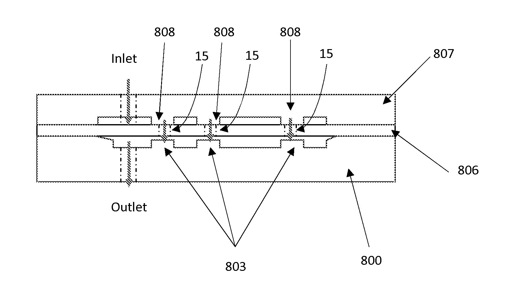
A fluid flow regulator (1) of the passive type is disclosed which has a fluid inlet adapted to be connected to a fluid reservoir and a fluid outlet (13) adapted to be connected to a patient's body. The regulator comprises a rigid substrate (2) and a resilient membrane (3) tightly linked together so as to define a cavity (6) there between which is disconnected to the fluid outlet while the membrane has a first surface (12) opposite the cavity which is connected to the fluid inlet. The membrane has a plurality of through holes (15) contiguous with the cavity, to define a pathway for a fluid from the fluid inlet to the fluid outlet, and is flexible so as to be able to come into contact with the substrate as a fluid applies a sufficient pressure on the first surface. The through holes are arranged such that, when the fluid pressure increases, they close one after the other to increase the regulator fluidic resistance so that a fluid flow rate would be substantially constant as a function of the pressure applied on the first surface within a predefined pressure range.

Description

TECHNICAL FIELD[0001]The present invention relates to a passive fluid flow regulator, more particularly of the type used in the field of drug delivery, the drug being either liquid or gaseous, for instance for pain management. The flow regulator of the present invention can also be used for draining cerebrospinal fluid (CSF) for hydrocephalus patient. The invention further relates to a fabrication process of such a fluid flow regulator as well as to a device comprising the latter.BACKGROUND ART[0002]Passive drug infusion devices, in contrast to active ones, do not rely on a pump to deliver a drug but rather on a pressurized drug reservoir. A known problem of these passive devices is that the drug flow rate to a delivery location, which may be a patient's body for instance, may vary as a function of the amount of drug remaining in the reservoir as far as the pressure in the reservoir depends on this amount. Such passive devices are thus usually provided with a fluid flow regulator to...

Claims


Application Information

Patent Timeline
IPC IPC(8): A61M5/168
CPCA61M5/145A61M5/16881A61M27/006A61M37/00A61M2205/0244F16K2099/0088F16K99/0013F16K99/0015F16K99/0026F16K99/0057F16K99/0001Y10T137/86718Y10T137/87306
Inventor CHAPPEL, ERIC
Owner DEBIOTECH SA
Learn More