
Spherical Braking System

a braking system and spherical technology, applied in the direction of braking systems, fluid actuated drum brakes, shock absorbers, etc., can solve the problems of generating braking torque, etc., and achieve the effect of increasing the stopping power, reducing the speed of the vehicle, and prolonging the life of the brake pads

Active Publication Date: 2011-06-09
LEWIS DESIGNS
View PDF10 Cites 4 Cited by
  • Summary
  • Abstract
  • Description
  • Claims
  • Application Information

AI Technical Summary

Benefits of technology

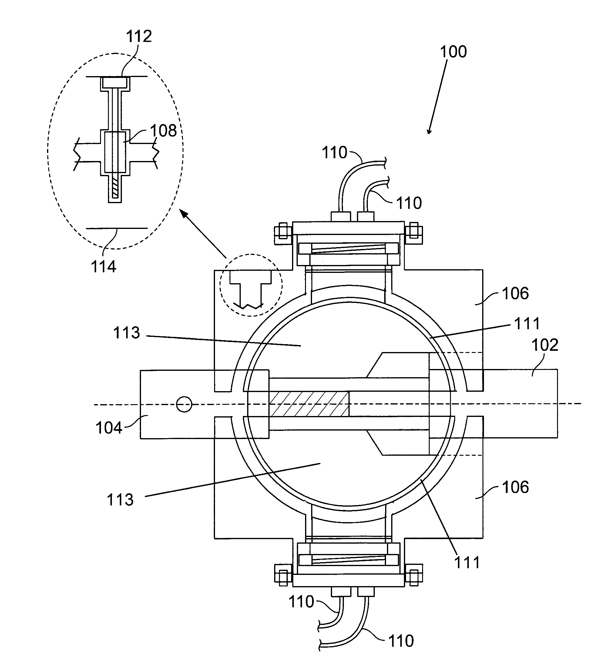
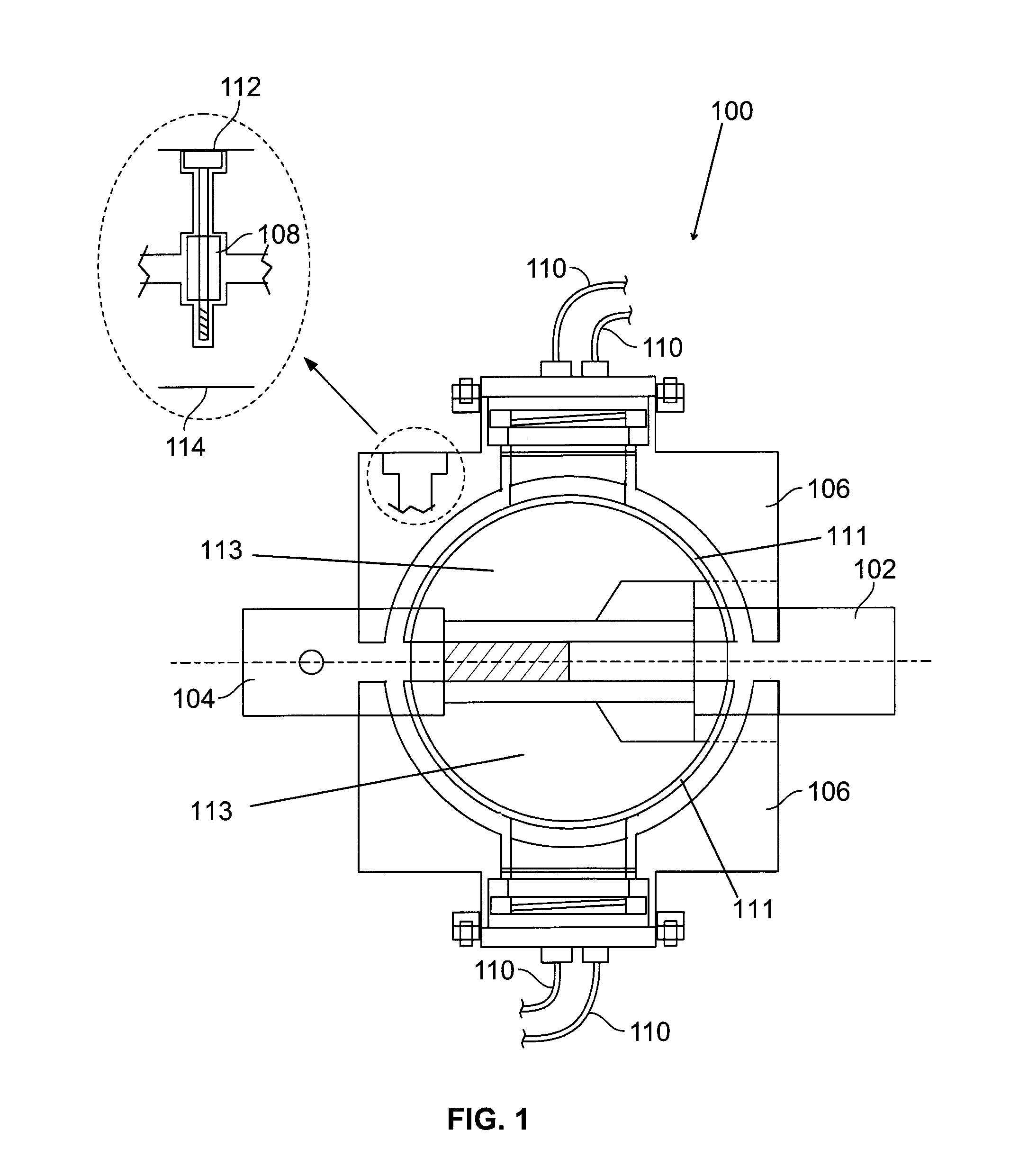
[0019]Exemplary embodiments of the present invention are directed towards a spherical braking system mounted on the drive shaft of a vehicle. The brake system of a vehicle is positioned at the drive shaft. A brake sphere is attached to the drive shaft and driven shaft near a wheel of a vehicle. In the preferred embodiment, four braking systems are utilized for each vehicle to provide maximum stopping power and longer life of the brake pads. Alternatively, one, two or more braking systems, depending on the vehicle's needs, can be used on a single vehicle.
[0021]A series of hydraulic lines projected from the hydraulic splitter are connected to the hydraulic line caps. Further, the hydraulic splitter is connected to the factory hydraulic system. A bleeder valve is positioned at the hydraulic cap for releasing trapped air present in the hydraulic lines. When the driver depresses the brake pedal, the fluid from the factory hydraulic system is transferred through the hydraulic lines to the hydraulic caps which results in the vertical movement of the brake pads causing a braking torque to be generated. This braking torque is applied to the brake sphere and hence the drive shaft which thereby slows the rotation of the drive shaft and driven shaft simultaneously and accordingly decreases the speed of the vehicle.DETAILED DESCRIPTION OF THE INVENTION

Problems solved by technology

When the driver depresses the brake pedal, the fluid from the factory hydraulic system is transferred through the hydraulic lines to the hydraulic caps which results in the vertical movement of the brake pads causing a braking torque to be generated.
This braking torque is applied to the brake sphere and hence the drive shaft which thereby slows the rotation of the drive shaft and driven shaft simultaneously and accordingly decreases the speed of the vehicle.

Method used


Image

  • Spherical Braking System
  • Spherical Braking System
  • Spherical Braking System

Examples


Embodiment Construction

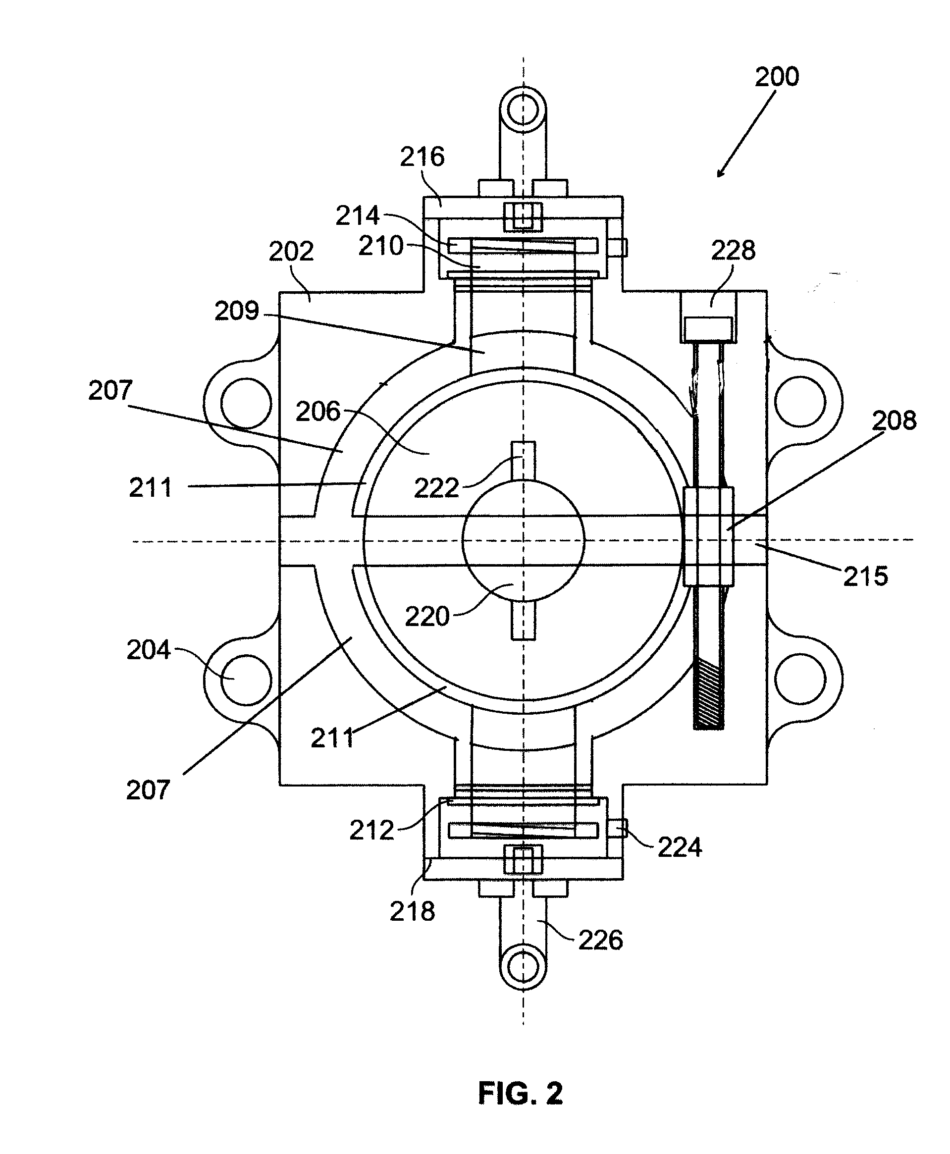
[0022]A spherical braking system mounted on a drive shaft of a vehicle includes a brake sphere pad positioned above and below a brake sphere and resting on at least one segment of a brake housing wherein, the brake housing includes a top segment and bottom segment coupled to mounting dogs by using a screw. A hydraulic cap installed on a threaded portion of a hydraulic shaft which is encircled by bushing and coupled near the brake sphere. A plurality of hydraulic lines connected from at least one hydraulic splitter is coupled to the hydraulic cap. When the driver depresses the brake pedal, pistons are forced into fluid chambers in the master cylinder. The resulting hydraulic pressure is transmitted through the hydraulic splitter and hydraulic lines to hydraulic caps into the hydraulic fluid chamber, increasing pressure, which results in the vertical movement of the brake pads causing a braking torque to be generated, slowing the rotation of the drive shaft and driven shaft simultaneo...


PUM


Abstract

A spherical braking system mounted on a drive shaft of a vehicle comprising a brake sphere pad positioned just above and below a brake sphere and resting on an at least one segment of a brake housing wherein, the brake housing includes a top segment and bottom segment coupled to mounting dogs by using screws. A hydraulic cap installed on a threaded portion of a hydraulic shaft which is encircled by bushing and coupled near a brake sphere. A plurality of hydraulic lines connected from at least one hydraulic splitter are coupled to the hydraulic cap. When the driver depresses the brake pedal, pistons are forced into fluid chambers in the master cylinder. The resulting hydraulic pressure is transmitted through the hydraulic splitter and hydraulic lines to hydraulic caps which results the vertical movement of the brake pads causes a braking torque to be generated, slowing the rotation of the drive shaft and driven shaft simultaneously, which therefore decreases the speed of the vehicle.

Description

CROSS-REFERENCE TO RELATED APPLICATIONS[0001]The present application claims the benefit of U.S. Provisional Application No. 61 / 267,508 filed on Dec. 9, 2009, which is incorporated herein by reference.FEDERALLY SPONSORED RESEARCH[0002]Not ApplicableBRIEF DESCRIPTION OF THE DRAWINGS[0003]These and other features, aspects and advantages of the present invention will become better understood with regard to the following description, appended claims, and accompanying drawings where:[0004]FIG. 1 is a diagram depicting a side view cross section of a braking system.[0005]FIG. 2 is a diagram depicting a front view cross section of a braking system.[0006]FIG. 3 is a diagram depicting a top view cross section of a braking system.[0007]FIG. 4 is a diagram of front view cross section depicting a set of measurements in accordance with an example of the present invention.[0008]FIG. 5 is a diagram of top view cross section depicting overall outer dimensions in accordance with an example of the pres...

Claims


Application Information

Patent Timeline
IPC IPC(8): F16D51/24
CPCB60T1/062F16D2121/02F16D63/00
Inventor LEWIS, AARON J.
Owner LEWIS DESIGNS
Learn More