High Power Waveguide Polarizer With Broad Bandwidth and Low Loss, and Methods of Making and Using Same

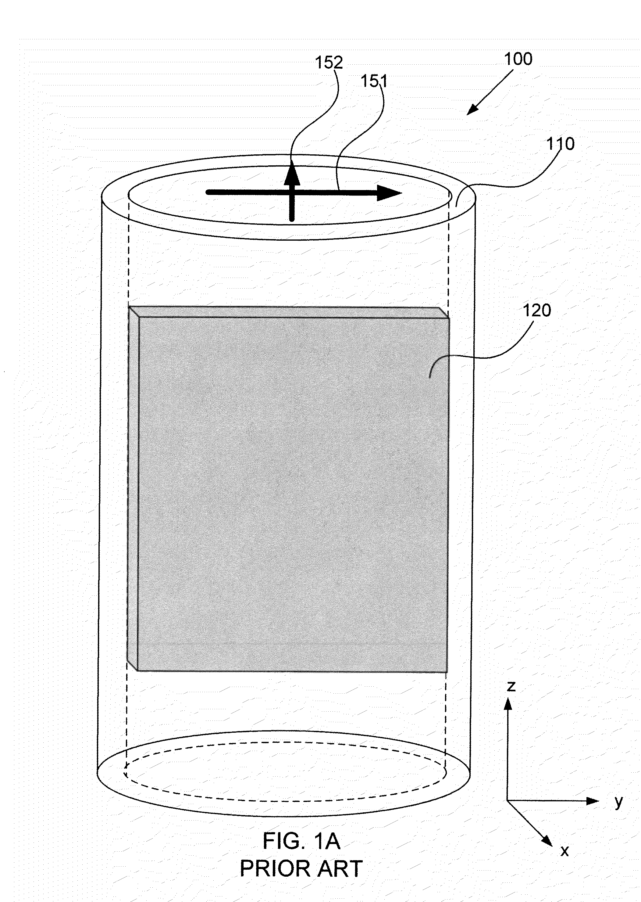
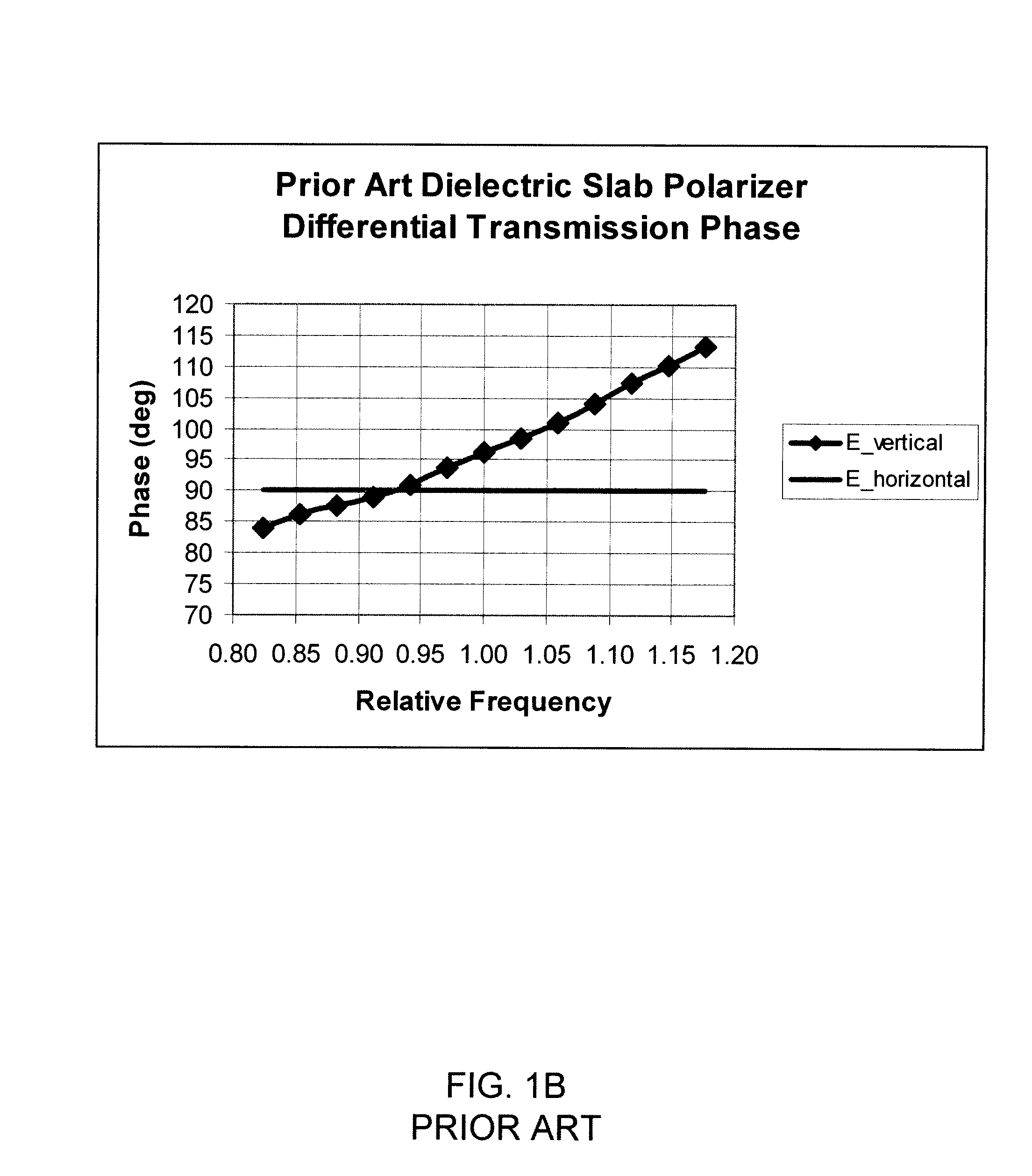
a waveguide polarizer, broad bandwidth technology, applied in waveguide devices, basic electric elements, electrical apparatus, etc., can solve the problems of elliptic wave, useful bandwidth less than 1%, and the monotonic increase of the differential phase shift induced by the slab b>120/b>, and achieve high-power waveguide polarizers, low loss, and broad bandwidth

Active Publication Date: 2011-06-09
THE AEROSPACE CORPORATION
View PDF15 Cites 19 Cited by
  • Summary
  • Abstract
  • Description
  • Claims
  • Application Information

AI Technical Summary

Benefits of technology

[0012]Embodiments of the invention provide high power waveguide polarizers with broad bandwidth and low loss, and methods of making and using same. Specifically, embodiments of the invention provide a compact waveguide polarizer that includes a hollow waveguide body and at least one ridge, for example, a pair of ridges, three ridges, or two pairs of ridges, disposed along the interior of the waveguide body. Each ridge includes on its upper surface a plurality of spaced projections, such as cylindrical or rectangular posts, or serrations. The ridges and spaced projections together produce a broad band differential phase shift between two orthogonal modes propagating through the waveguide body. Specifically, the spaced projections provide a small capacitive reactance that offsets the inductive loading of the lower portions of the ridges. As a result, a mode propagating parallel to the ridges accumulates a phase delay relative to a mode propagating orthogonal to the ridges that is substantially independent of wavelength over a relatively wide bandwidth. The differential phase delay may easily be tuned by adjusting the length of the projections. The bandwidth of the polarizer may in some embodiments be enhanced by configuring the projections so as to have a narrower width than the width of the ridge on which they are disposed. Additionally, the polarizers may be inexpensively fabricated, are compact, have no dielectric losses, may accept high power fields, and may be used in a wide variety of environmental conditions.

Problems solved by technology

Tolerances and errors in the conversion process typically result in some ellipticity of the wave, regardless of the desired polarization.
Although this technique is relatively simple, only waves having a wavelength matched to the length of the particular waveguide will accumulate the 90-degree phase delay, resulting in a useful bandwidth of less than 1%.
One drawback of polarizer 100 is that differential phase shift induced by slab 120 monotonically increases with frequency.
Another drawback of polarizer 100 is that parallel mode 151 must propagate within slab 120.
Dielectric slab 120 is also susceptible to outgassing and to damage, requiring the power of the incoming wave to be maintained below the damage threshold of the dielectric material.
Furthermore, repeatability of the dielectric material properties and dimensions may be poor, causing performance to vary from polarizer to polarizer.
These structures tend to be relatively large and costly from a material standpoint.
Thus, prior art polarizers suffer from a number of deficiencies, including low bandwidth, high loss, low power handling capability, and / or large size.
As a result, a mode propagating parallel to the ridges accumulates a phase delay relative to a mode propagating orthogonal to the ridges that is substantially independent of wavelength over a relatively wide bandwidth.

Method used


Image

  • High Power Waveguide Polarizer With Broad Bandwidth and Low Loss, and Methods of Making and Using Same
  • High Power Waveguide Polarizer With Broad Bandwidth and Low Loss, and Methods of Making and Using Same
  • High Power Waveguide Polarizer With Broad Bandwidth and Low Loss, and Methods of Making and Using Same

Examples


Embodiment Construction

Overview

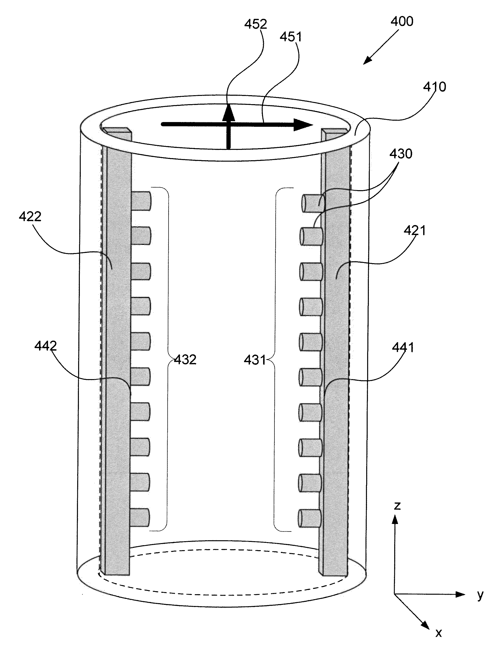
[0044]Embodiments of the invention provide waveguide polarizers having significantly improved performance relative to the prior art polarizers described above. First, the inventive waveguide polarizers have a significantly broader bandwidth than previously achieved with slab, stepped ridge, or septum polarizers, for example. This broader bandwidth is achieved, in part, by providing, within a hollow cylindrical waveguide body, at least one ridge, for example, a pair of ridges, that include a plurality of spaced projections on their upper surfaces. As described in greater detail below, the projections may be cylindrical or rectangular posts, or serrations, for example, that protrude from a lower portion of the ridges. Like the ridges discussed above with respect to FIG. 2A, the inventive ridges induce a differential phase delay in orthogonal modes traveling through the waveguide body. However, the spaced projections modify the wavelength dependence of the phase delay induced b...


PUM


Abstract

Embodiments of the invention provide high power waveguide polarizers with broad bandwidth and low loss, and methods of making and using the same. Under one aspect of the present invention, a waveguide polarizer includes a hollow waveguide body having an interior surface; a first ridge disposed on the interior surface of the hollow waveguide body and having an inward-facing surface; and a first plurality of projections disposed on the inward-facing surface of the first ridge. The projections may have a width that is narrower than that of the ridge, and a length that is tunable. The length of the projections may be selected to induce about a 90-degree phase delay in a first mode propagating in a plane parallel to the first ridge relative to a second mode propagating in a plane perpendicular to the first ridge.

Description

STATEMENT OF GOVERNMENT INTEREST[0001]This invention was made with Government support under contract FA 8802-04-C-0001 awarded by the Department of the Air Force. The Government has certain rights in the invention.FIELD OF THE INVENTION[0002]This application generally relates to waveguide polarizers, and methods of making and using same.BACKGROUND OF THE INVENTION[0003]In general, guided-wave polarizer technology converts a circularly-polarized wave into a linear-polarized wave while maintaining orthogonality of the two possible senses of each polarized wave. For example, a guided-wave polarizer may convert a left-hand, circularly-polarized (LHCP) wave into a horizontal (H) linearly-polarized wave; alternatively, such a polarizer may convert a right-hand, circularly-polarized (RHCP) wave into a vertical (V) linearly-polarized wave. As is known in the art, such polarization conversion is based on decomposing circularly polarized waves into a superposition of two orthogonal, linearly ...

Claims


Application Information

Patent Timeline
Patent Type & Authority Applications(United States)
IPC IPC(8): H01P1/165
CPCH01P1/173H01P1/171
Inventor LANGE, MARK J.
Owner THE AEROSPACE CORPORATION
Why Eureka
Try Eureka