Formed body with curved surface shape, method of producing the formed body, front cover for vehicle lighting device, and method of producing the front cover

a technology of curved surfaces and formed bodies, which is applied in the direction of point-like light sources, transportation and packaging, lighting and heating apparatus, etc., can solve the problems of poor productivity, need improvement, and vapor-depositing or sputtering of conductive metals such as ito on the transparent electrode layer, so as to improve heat generation uniformity, reduce cost, and improve the effect of curved surface body conductivity

Active Publication Date: 2011-06-09
FUJIFILM CORP
View PDF5 Cites 34 Cited by
  • Summary
  • Abstract
  • Description
  • Claims
  • Application Information

AI Technical Summary

Benefits of technology

[0046]As described above, in the curved-surface body and the curved-surface body production method of the present invention, the substantially transparent conductor can be formed in the curved surface shape without wire breaking or the like, the conductivity of the curved-surface body can be improved, and a display or lighting device having a three-dimensional curved display surface can be obtained at low cost.
[0047]Furthermore, in the car light front cover of the present invention, the substantially transparent surface heat generation film can be formed on the curved surface, the heat generation uniformity can be improved, the migration problem can be solved, and the transparent heater can be inexpensively formed on the curved-surface body. The heat generator can be used in a windshield cover for a helmet, a car rear window, a tropical fish tank, etc. as well as in the car light front cover.

Problems solved by technology

The methods containing vapor-depositing or sputtering the conductive metal such as ITO on the transparent electrode layer to increase the conductivity (see, for example, Japanese Laid-Open Patent Publication Nos. 08-180974 and 09-147639) are poor in productivity and need improvement in this point.
Furthermore, the method using the busline requires an increased number of processes, thereby resulting in high cost.
However, there are fears of depletion of the ITO material, and thus an alternative material is demanded.
In addition, the vapor deposition process is disadvantageous in great loss.
The methods containing vapor-depositing or sputtering the conductive metal such as ITO to form the conductive layer (see, for example, Japanese Laid-Open Patent Publication No. 09-147639) are poor in productivity and need improvement in this point.
Such a conductive wire is visible to the naked eye, and the structure is disadvantageous in transparency.
However, a potential difference may be disadvantageously generated between adjacent conductive line portions to cause migration.

Method used


Image

  • Formed body with curved surface shape, method of producing the formed body, front cover for vehicle lighting device, and method of producing the front cover
  • Formed body with curved surface shape, method of producing the formed body, front cover for vehicle lighting device, and method of producing the front cover
  • Formed body with curved surface shape, method of producing the formed body, front cover for vehicle lighting device, and method of producing the front cover

Examples


modification examples

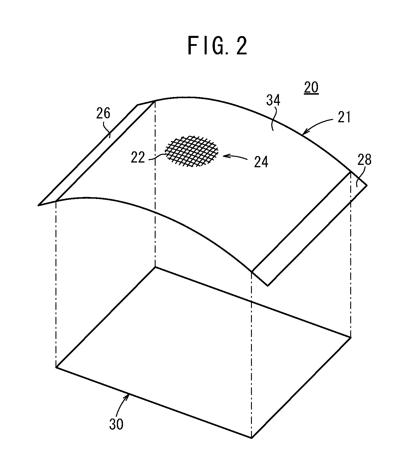
[0172]Several modification examples of the heat generator 20 used in the front cover 10 of this embodiment will be described below.

[0173]A heat generator according to a first modification example has a carbon nanotube layer containing a large number of dispersed carbon nanotubes instead of the mesh pattern 24 containing the thin metal wires 22. In this example, the amount and dispersion ratio of the carbon nanotubes are preferably controlled so that the heat generator 20 has a surface resistance of 10 to 500 ohm / sq and an electrical resistance of 12 to 120 ohm.

[0174]For example, the carbon nanotubes may be used in the form of a carbon nanotube dispersion described in Japanese Patent No. 3665969.

[0175]The carbon nanotubes include straight and curved multi-walled carbon nanotubes (MWNTs), straight and curved double-walled carbon nanotubes (DWNTs), straight and curved single-walled carbon nanotubes (SWNTs), and various compositions thereof, and common by-products obtained in carbon nan...

examples

[0201]The present invention will be described more specifically below with reference to Examples. Materials, amounts, ratios, treatment contents, treatment procedures, and the like used in Examples may be appropriately changed without departing from the scope of the invention. The following specific examples are therefore to be considered in all respects as illustrative and not restrictive.

first example

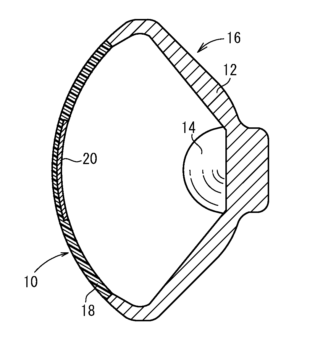
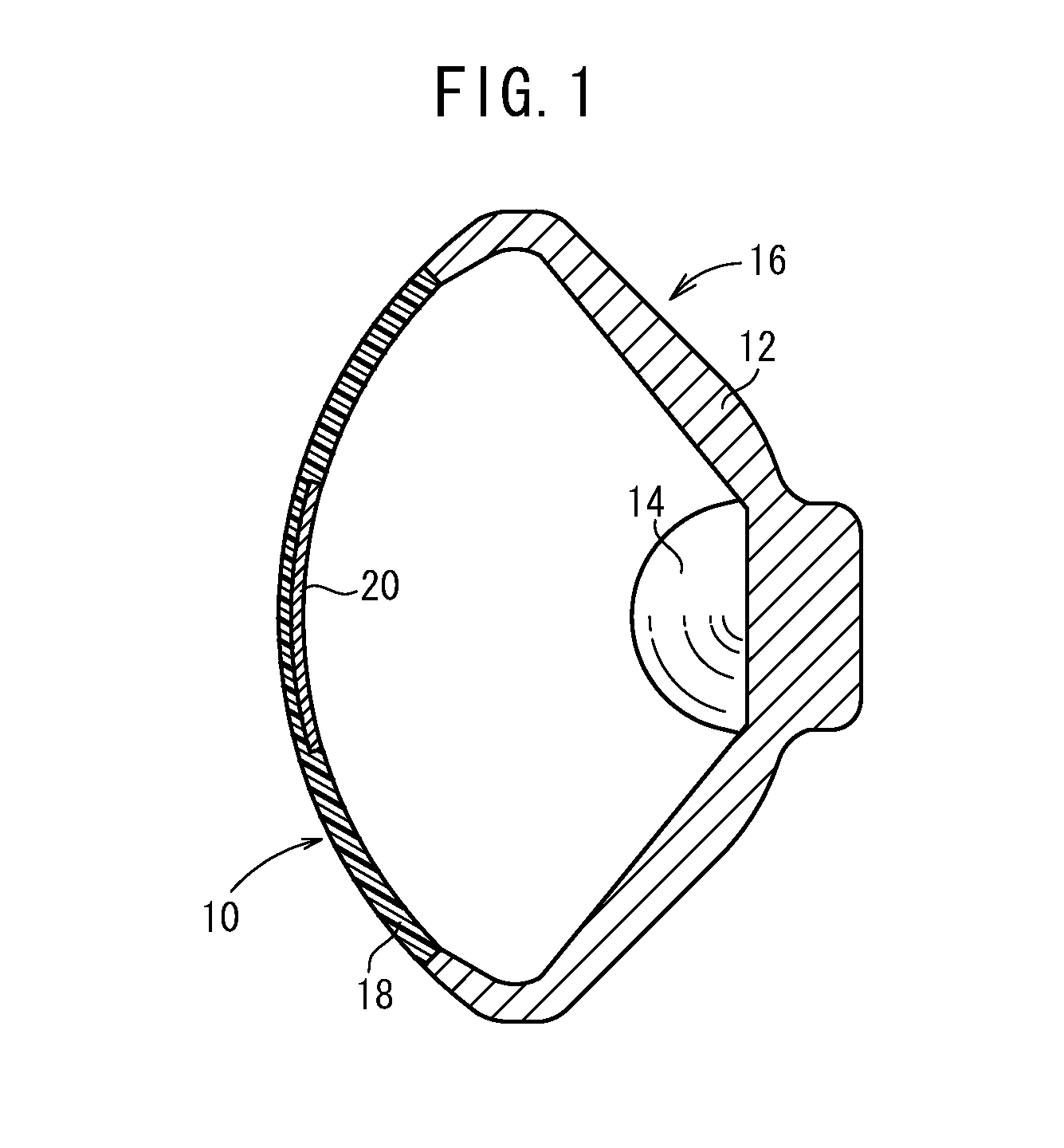
[0202]A front cover containing a heat generator 20 according to Example 1 and a front cover according to Reference Example 1 were produced, and the electrode distances and the temperature distributions thereof were measured to confirm the effects of the embodiment.


PUM

PropertyMeasurementUnit
transparentaaaaaaaaaa
diameteraaaaaaaaaa
widthaaaaaaaaaa

Abstract

A formed body having a curved surface, a method of producing the formed body, a front cover for a vehicle lighting device, and a method of producing the front cover. A front cover (10) for a vehicle lighting device, mounted to a front opening in a vehicle lighting device (16) having a lamp body (12) and a light source (14) which is provided in the lamp body (12), wherein a heat generating body (20) is provided in a substantially rectangular region of that surface of the front cover which faces the light source (14). The heat generating body (20) maintains the relationship of Ra=(2 R0), where R0 is the electric resistance value (initial value) of the heat generating body (20) before the heat generating body is elongated and Ra is the electric resistance value of the heat generating body (20) after the heat generating body is elongated 5%.

Description

TECHNICAL FIELD[0001]The present invention relates to a curved-surface (formed) body having a transparent conductor useful for a display device, a lighting device, etc., a method for producing the curved-surface (formed) body, a car light (vehicle lighting device) front cover having a transparent heat generator excellent in visibility and heat generation, and a method for producing the front cover.BACKGROUND ART[0002]In recent years, in liquid crystal displays, organic and inorganic electroluminescence devices, electronic papers, etc., a film or a glass substrate having a transparent conductive layer has been used as an electrode on the light-emitting side (see, for example, Japanese Laid-Open Patent Publication Nos. 08-180974, 09-147639, 10-162961, and 11-224782).[0003]The transparent conductive layer is generally composed of an indium tin oxide, a zinc oxide, a tin oxide, etc., and has to be thick and uniform to achieve low resistance. Thus, the layer is disadvantageous in low lig...

Claims


Application Information

Patent Timeline
Patent Type & Authority Applications(United States)
IPC IPC(8): B60Q1/02B29C45/14H05K1/00H05K1/09B82Y30/00B82Y99/00F21Y101/00
CPCH05B3/84F21S48/1233F21S48/10F21V29/02F21S48/34F21V29/90F21V3/00F21S41/28F21S45/60F21V3/06Y10T428/24802Y10T428/24917
Inventor OHTANI, SUMIOKURIKI, TADASHITOKUNAGA, TSUKASA
Owner FUJIFILM CORP
Why Eureka
Try Eureka