Optical grade surfacing tool

a technology of optical grade and surfacing tool, which is applied in the direction of grinding machine components, grinding machines, abrasion apparatus, etc., can solve the problems of difficulty in avoiding certain appearance defects and appearance defects remain, and achieve the effect of high performance and high quality of surfacing

Active Publication Date: 2011-06-09
ESSILOR INT CIE GEN DOPTIQUE
View PDF6 Cites 22 Cited by
  • Summary
  • Abstract
  • Description
  • Claims
  • Application Information

AI Technical Summary

Benefits of technology

[0017]This enables the tool of the invention to offer particularly high performance, notably in terms of maintaining contact with the surface to be worked, including when the latter has strong variations of altitude, for example when it is one face of a spectacle lens for correcting the vision of a wearer suffering from presbyopia, myopia and astigmatism.
[0018]Thanks to its performance in terms of maintaining contact with the surface to be worked, the tool of the invention makes it possible to obtain a particularly high quality of surfacing, in particular but not exclusively for concave surfaces.

Problems solved by technology

The results achieved by these tools are generally satisfactory, but it is sometimes difficult to avoid certain defects of appearance, namely the orange skin effect and the sheeplike effect.
The resulting tool achieves an improvement in surface appearance, but in some circumstances such appearance defects remain.

Method used


Image

  • Optical grade surfacing tool
  • Optical grade surfacing tool
  • Optical grade surfacing tool

Examples


Embodiment Construction

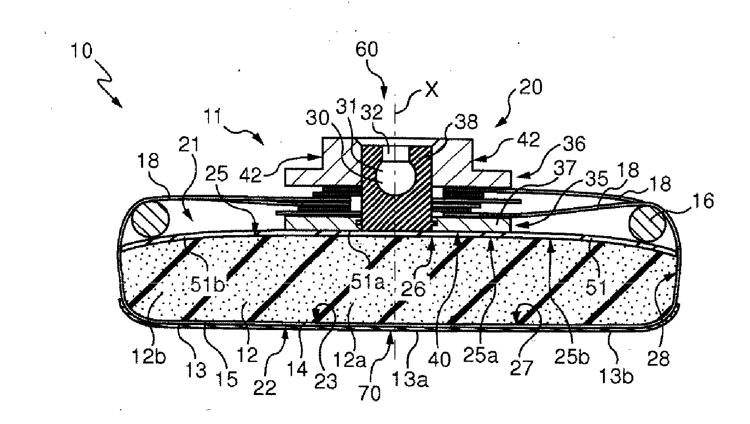
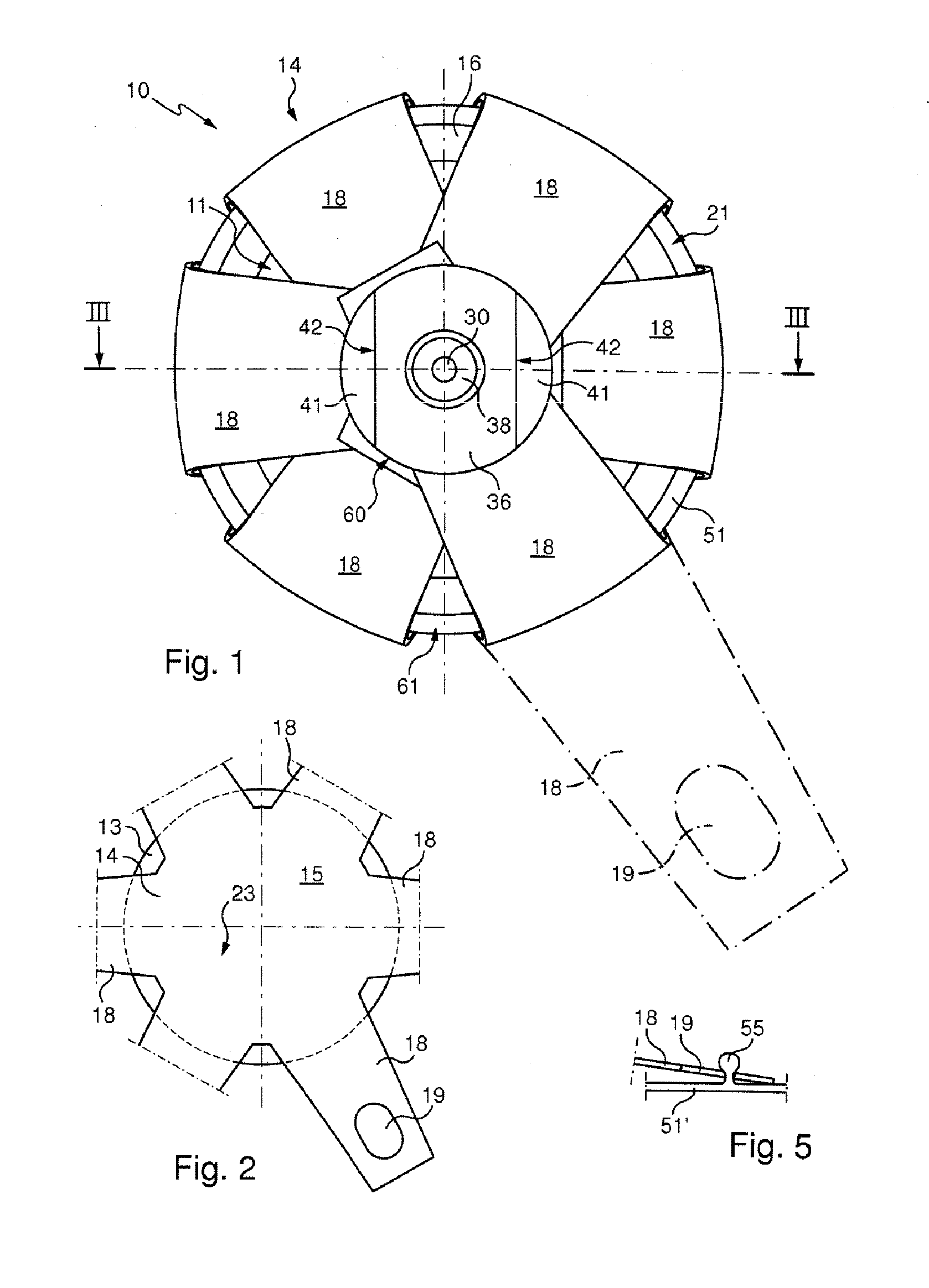
[0036]The tool 10 shown in the drawings includes a base 11, an elastically compressible interface 12 attached to the base 11, a flexible pad 13 attached to the interface 12 on the opposite side to the base 11, a membrane 14 for tensioning the pad 13 and a deformable ring 16 disposed between the peripheral part of the interface 12 and the straps 18 of the membrane 14.

[0037]With the exception of the membrane 14, the general shape of the tool 10 is that of a circular cylinder and the tool has an axis X of symmetry that defines a longitudinal direction.

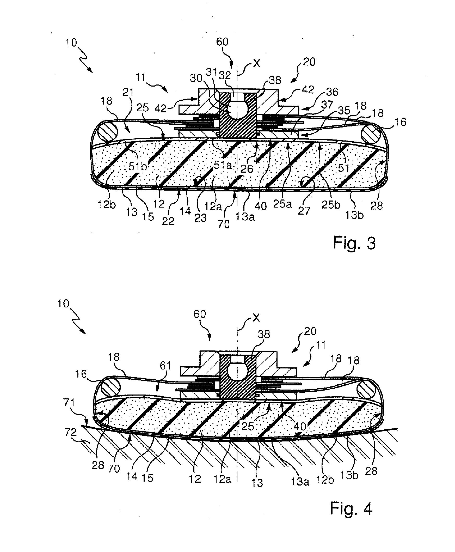
[0038]The base 11 includes a rigid core 20 and a flexible backing plate 21. On the side seen at the bottom in FIG. 3, the base 11 has a transverse end surface 25.

[0039]In the absence of stress, i.e. in a position that is not represented because the tensioning membrane 14 acts on the backing plate 21 including in the rest position shown in FIGS. 1 and 3, the end surface 25 is plane.

[0040]The interface 12 has a first end surface 26, a secon...


PUM


Abstract

An optical-grade surfacing tool includes: a rigid holder (60); an elastically compressible interface (12) secured to the rigid holder (60); and a flexible pad (13) that can be applied against a surface to be machined (71) and secured to the interface (12) opposite the rigid holder (60). The pad (13) is carried by an elastically extensible membrane (14) including: a central plate (15); and a plurality of straps (18) each radially protruding from the periphery of the plate (15) and each having a distal portion engaged with a fastening element (38), each strap (18) rotating about the side surface (28) of the interface (12) and extending up to the fastening element, each strap (18) being taut.

Description

FIELD OF THE INVENTION[0001]The invention relates to optical grade surfacing, for surfaces such as a face of an ophthalmic lens, a camera lens, an instrument for observing distant objects or a semiconductor substrate.[0002]Surfacing means any operation aiming to modify the state of a previously worked surface. It is a question in particular of polishing, grinding or fine grinding operations aiming to modify (reduce or increase) the roughness of the surface and / or to reduce undulation thereof.TECHNOLOGICAL BACKGROUND[0003]There is already known, in particular from French patent application 2 834 662, to which corresponds US patent application 2005 / 0101235, French patent application 2 857 610, to which corresponds US patent application 2006 / 0154581, and French patent application 2 900 356, to which corresponds international application WO 2007 / 128894, a tool for surfacing an optical surface, the tool including: a rigid support having a transverse end surface; an elastically compressib...

Claims


Application Information

Patent Timeline
Patent Type & Authority Applications(United States)
IPC IPC(8): B24B41/02
CPCB24B13/02B24D13/147B24D9/08
Inventor MEYNEN, MATHIEU
Owner ESSILOR INT CIE GEN DOPTIQUE
Why Eureka
Try Eureka