Pyrolysis systems, methods, and resultants derived therefrom

a pyrolysis system and pyrolysis technology, applied in the field of pyrolysis systems and methods, can solve the problems of limiting the range of feedstocks that prior art pyrolysis systems may process, long time-consuming and labor-intensive problems, and achieve the effect of easy conformation

Active Publication Date: 2011-06-09
TUCKER RICHARD D
View PDF16 Cites 39 Cited by
  • Summary
  • Abstract
  • Description
  • Claims
  • Application Information

AI Technical Summary

Benefits of technology

[0017]In accordance with a still further aspect of the present invention, layers of communications control and data gathering control at least one of the pieces of equipment or machines, groups of machines within a plant, an entire plant operation, and a group of plants within a region. In an embodiment, the control system provides uniform and standard instrumentation and data for the plant operation on a regional or global basis. One objective is to provide the energy and product data available from these plants in a historical block of profile data such that the gas and/or electrical energy data may be easily conformed to trading floor data models. In an embodiment, standard communication protocols are used to provide seamless integration of energy generation and energy metering to advanced metering infrastructure. These may be managed through the use of standard or manufacturer defined tables, user defined tables, extended user defined tables, standard procedures and manufacturer procedures, pending table and pending procedure, bi-directional message and uni-directional

Problems solved by technology

However, obtaining consistency in the pyrolysis products has long been a problem.
Prior systems have attempted to pass a gasification agent through a fluidized bed of solid; however, this requires a highly granular and reactive fuel for gasification, and, as such, is limited in its application.
Likewise, high and low-temperature pyrolysis processes are each better suited to pyrolizing different feedstocks, limiting the range of feedstocks that prior art pyrolysis systems

Method used


Image

  • Pyrolysis systems, methods, and resultants derived therefrom
  • Pyrolysis systems, methods, and resultants derived therefrom
  • Pyrolysis systems, methods, and resultants derived therefrom

Examples


Embodiment Construction

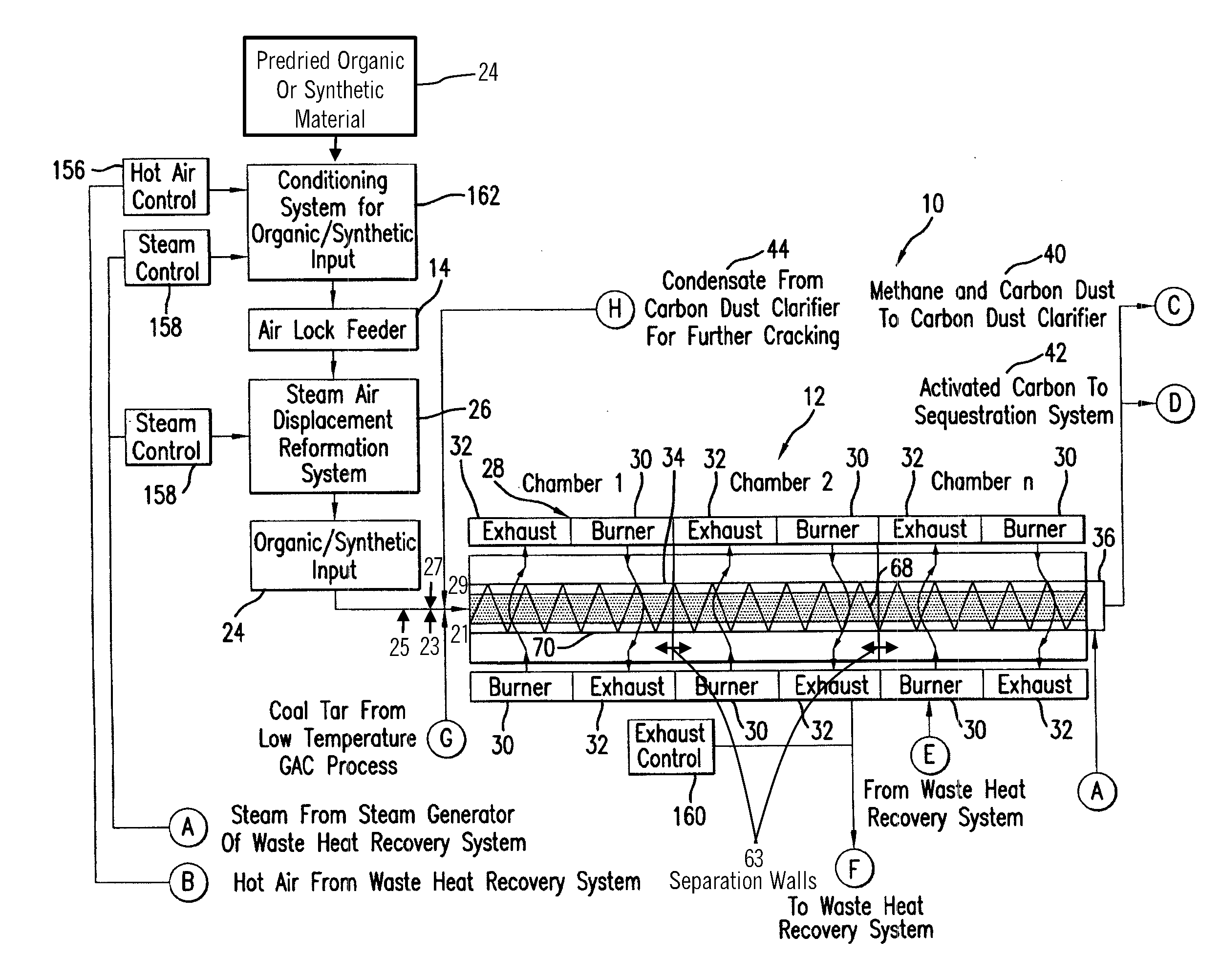
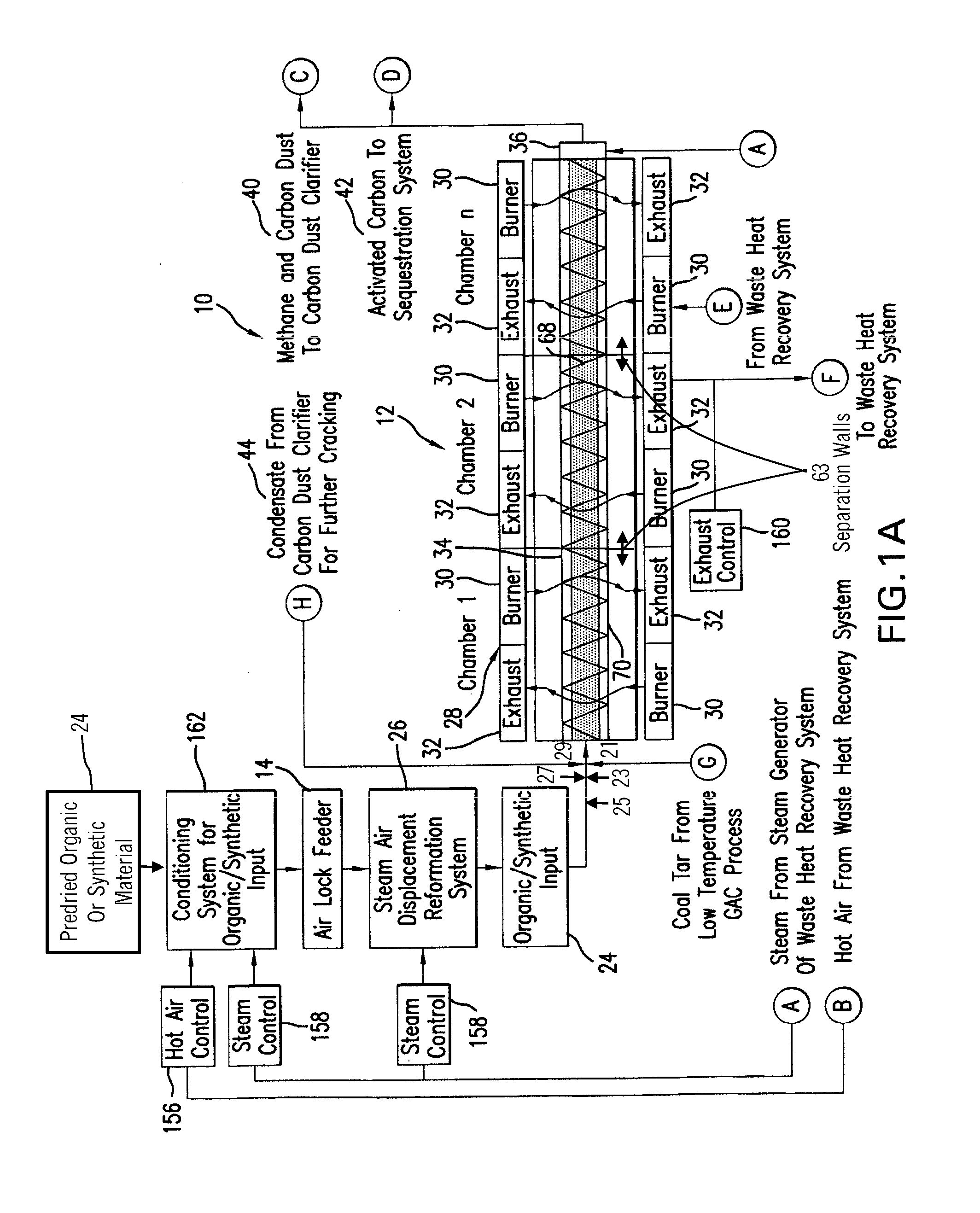
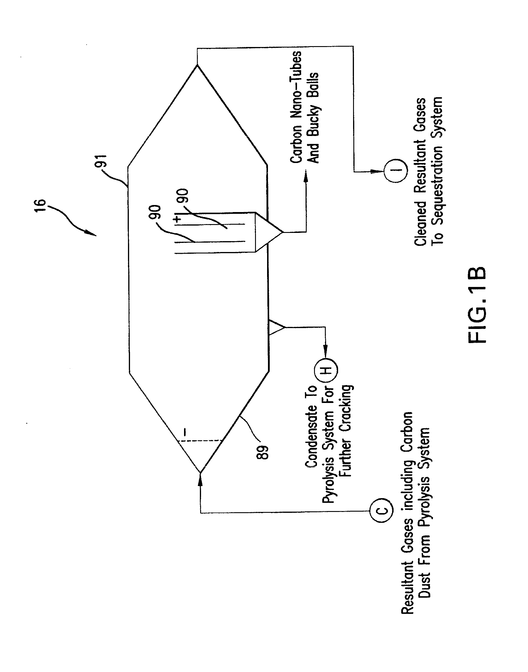
[0034]FIGS. 1A-1F are schematic diagrams showing components of a combined cycle carbonaceous feedstock conversion system 10 according to an embodiment of the present invention. The system 10 includes a high-temperature pyrolysis unit 12 that receives carbonaceous feedstock through an airlock feeder 14 with injector 25 (FIG. 2A) providing a sequestration agent for controlled internal sequestration of noxious elements and compounds that produce a sulfur and mercury-free gas product containing methane and a solid product containing activated carbon or non-activated carbon, depending upon the type of feedstock and whether “non-wetting” agent injector 27 (FIG. 2A) is used to induce the non-wetting action. Also, the system 10 includes further injectors of viscous organic material 23 (FIG. 2A) for enhanced gas energy content and a steam injector 26 for positive pressure and steam reformation. The system 10 further includes a dust clarifier 16 for collecting carbon nanostructures from the g...


PUM

PropertyMeasurementUnit
Temperatureaaaaaaaaaa
Pressureaaaaaaaaaa
Viscosityaaaaaaaaaa

Abstract

The present invention provides a process for the controlled gasification of a carbonaceous feedstock, including: pyrolizing the feedstock to produce a gas product and a solid product, wherein the gas product includes methane and noxious chemicals and the solid product includes carbon; and controlling the pyrolizing step using feedback related to constituents of the gas product. The present invention also provides a system for the controlled gasification of a carbonaceous feedstock, including: a pyrolysis unit including a heater and a conveyor for transporting the feedstock through the heater; a resultant chamber disposed downstream of the pyrolysis unit for separating gas products and solid products; means for adjusting the temperature of the solid products; and a filter for sequestering noxious materials from the gas products, wherein the filter uses at least some of the solid products to filter at least a portion of the gas products.

Description

CROSS-REFERENCE TO RELATED APPLICATIONS[0001]The present patent application / patent claims the benefit of priority of U.S. Provisional Patent Application No. 61 / 268,033, filed on Jun. 8, 2009, the contents of which are incorporated in full by reference herein. The present patent application / patent is a continuation-in-part of U.S. patent application Ser. No. 12 / 048,906, filed on Mar. 14, 2008, which claims the benefit of priority of U.S. Provisional Patent Application No. 60 / 906,691, filed on Mar. 14, 2007, U.S. Provisional Patent Application No. 60 / 997,291, filed on Oct. 3, 2007, and U.S. Provisional Patent Application No. 61 / 007,965, filed on Dec. 17, 2007, the contents of all of which are incorporated in full by reference herein.FIELD OF THE INVENTION[0002]The present invention relates generally to a system and method for producing methane gas and carbon products from carbonaceous feedstock.BACKGROUND OF THE INVENTION[0003]Techniques for the partial pyrolysis of feedstocks, as wel...

Claims


Application Information

Patent Timeline
IPC IPC(8): C08K3/04C01B31/02C10B57/00C10B57/12C10B1/10B82Y30/00
CPCB82Y30/00Y02E50/14C01B31/02C01B31/0206C01B31/08C10B47/30C10B47/44C10B53/00C10B53/02C10B53/04C10G1/002C10G1/02C10G1/10C10G2300/1003C10G2300/1011B82Y40/00C01B32/05C01B32/15C01B32/30Y02E50/10Y02P20/129Y02P30/20
Inventor TUCKER, RICHARD D.
Owner TUCKER RICHARD D
Why Eureka
Try Eureka