
Portable magnetic field stimulator

a stimulator and magnetic field technology, applied in the field of portable magnetic field stimulators, can solve the problems of muscle contraction and inability to apply on different surfaces

Inactive Publication Date: 2011-06-09
SOUTHERN TAIWAN UNIVERSITY OF TECHNOLOGY
View PDF6 Cites 2 Cited by
  • Summary
  • Abstract
  • Description
  • Claims
  • Application Information

AI Technical Summary

Benefits of technology

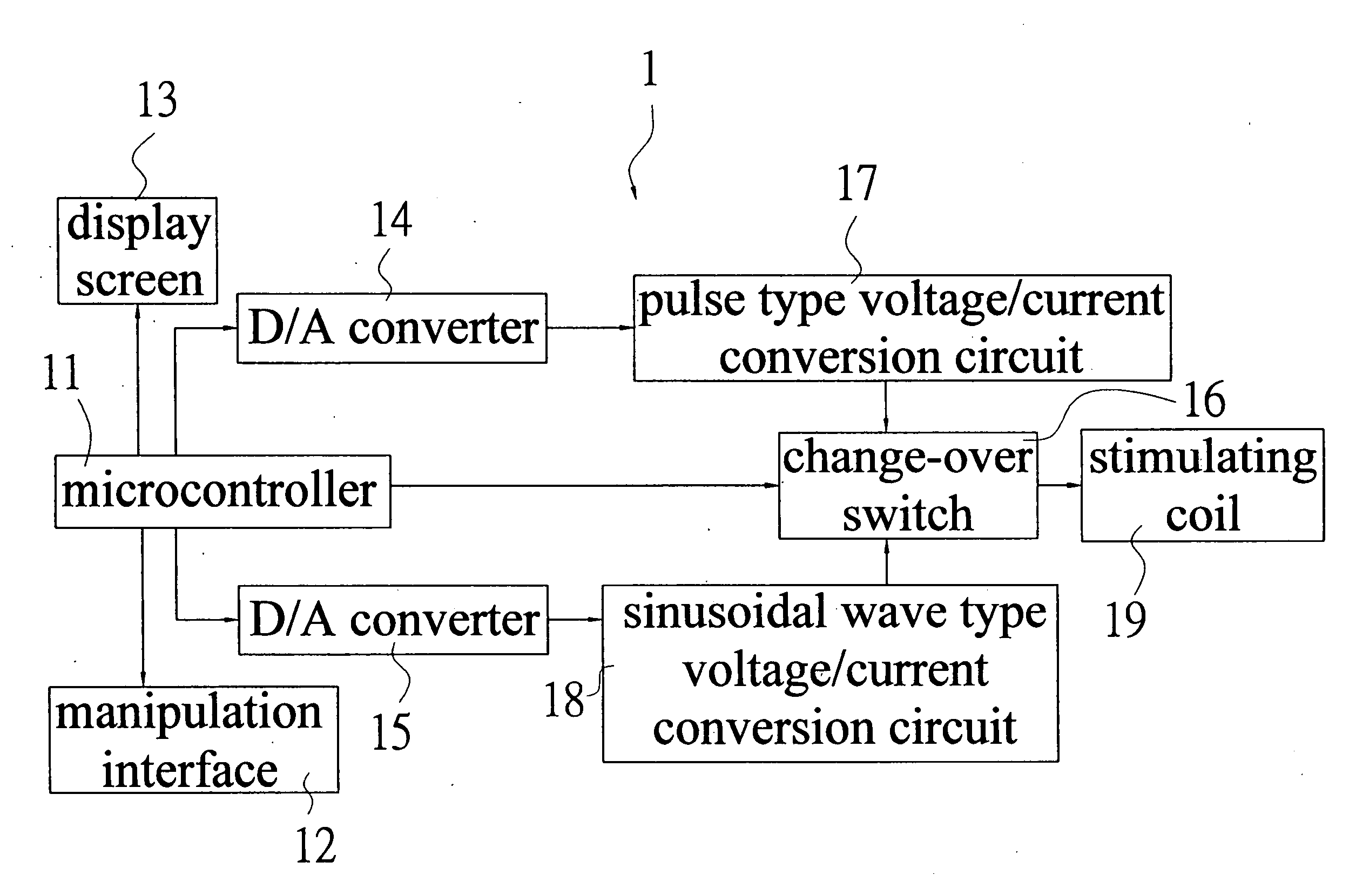
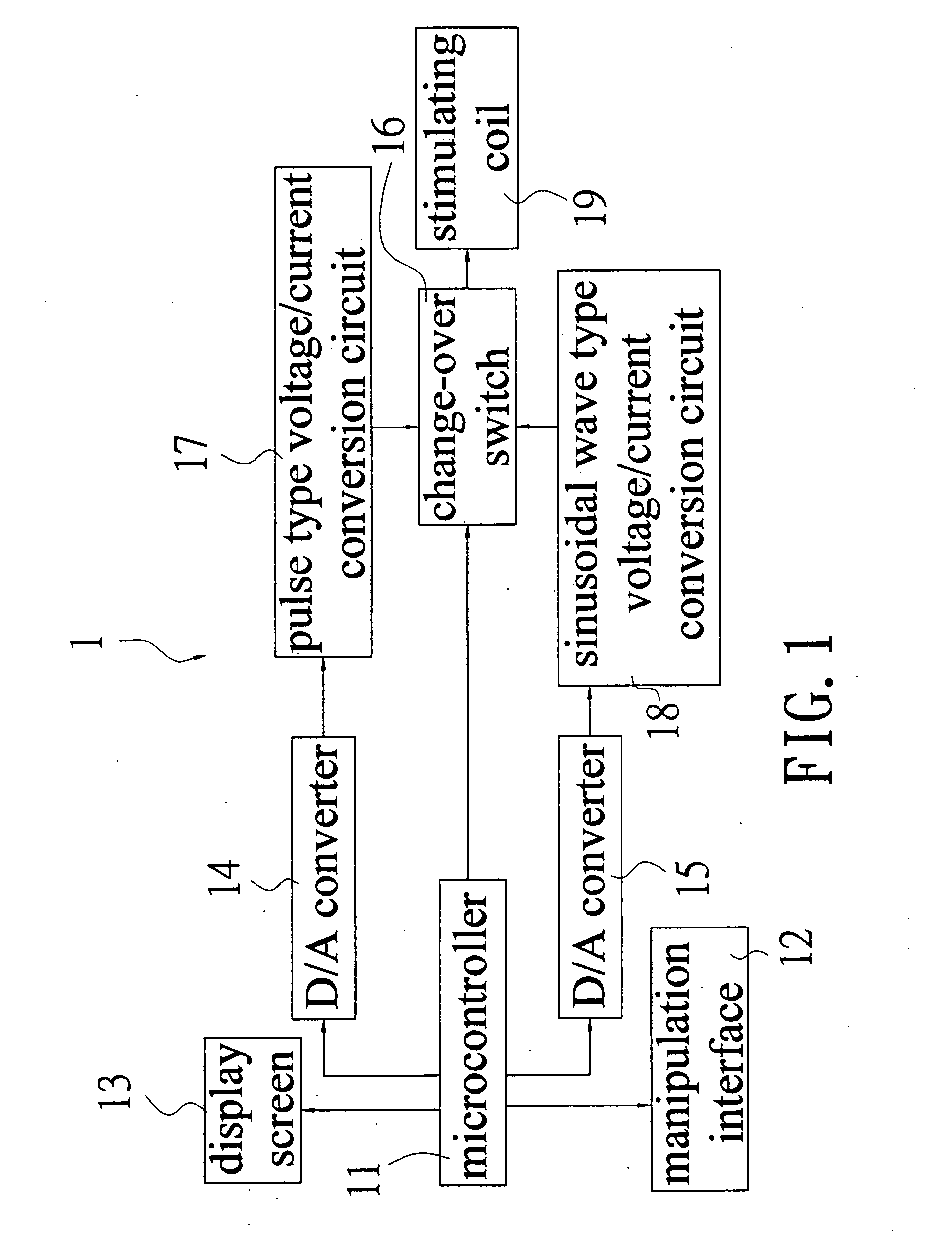
[0010]The portable magnetic field stimulator of the present invention essentially has a microcontroller served as core part which sets sinusoidal wave or pulse voltage signals of different frequency, intensity, duty cycle through a manipulation interface, and inputs the signals to a pulse type voltage / current conversion circuit or a sinusoidal wave type voltage / current conversion circuit. Finally, the current is transmitted to a stimulating coil to produce sinusoidal wave or pulse wave magnetic field having direct current level with a frequency of 1˜2 kHz and with a magnetic flux of 1˜300 Gauss. Thereby, not only the variation of frequency can be controlled but also the other subtle parameters such as duty cycle, multi wave form switching are also able to be manipulated and set, and different stimulating wave form of sinusoidal wave or pulse can also be produced. In addition, it can be applied in diversified symptoms. It can increase more practical effectiveness in the integral implementation and usage thereof.

Problems solved by technology

Sufficiently big electric current intensity will cause shrinking of muscles.
1. In the above structure, there are few variable items on stimulating parameter. Only the variation of frequency can be controlled. The other subtle parameters such as duty cycle, multi wave form switching is not included in the controllable parameter items.
2. Their application field is unitary, most of them are only developed for the facilitation of bone heal over, and are unable to be applied on different symptoms.
3. Most of the internal circuit in the magnetic field stimulator utilizes RC charge and discharge method for producing magnetic field such that only sole stimulating wave form can be produced.

Method used


Image

  • Portable magnetic field stimulator
  • Portable magnetic field stimulator
  • Portable magnetic field stimulator

Examples


Embodiment Construction

[0014]The technical content, objects and effectiveness of the present invention will become more apparent by the detailed description of a preferred embodiment of the present invention in conjunction with the accompanying drawings.

[0015]FIG. 1 is a schematic block diagram showing the portable magnetic field stimulator of the present invention. As shown in FIG. 1, the magnetic field stimulator (1) is essentially provided with a microcontroller (11). A manipulation interface (12) is connected to the microcontroller (11) for users to conduct the setting and manipulating for each item. A display screen (13) is connected with the microcontroller (11) so as to display the status of each manipulation. D / A converters (14), (15) and a change-over switch (16) are also respectively connected to the microcontroller (11), in which the D / A converter (14) is connected with a pulse type voltage / current conversion circuit (17), while the D / A converter (15) with a sinusoidal wave type voltage / current...


PUM


Abstract

The portable magnetic field stimulator of the present invention has a microcontroller which sets sinusoidal wave or pulse voltage signals of different frequency, intensity, duty cycle through a manipulation interface, and inputs the signals to a pulse type voltage / current conversion circuit or sinusoidal wave type voltage / current conversion circuit. Finally, the current is transported to the stimulating coil to produce sinusoidal wave or pulse wave magnetic field having direct current level with frequency 1˜2 kHz and with magnetic flux 1˜300 Gauss. Thereby, not only the variation of frequency can be controlled but also the other subtle parameters such as duty cycle, multi wave form switching are also able to be manipulated and set, and different stimulating wave form of sinusoidal wave or pulse can also be produced. In addition, it can be applied in diversified symptoms.

Description

BACKGROUND OF THE INVENTION[0001]1. Field of the Invention[0002]The present invention relates to a portable magnetic field stimulator, particularly to a novel portable magnetic field stimulator which can produce sinusoidal wave or pulse wave voltage signals of different frequency, strength, duty cycle, and can produce sinusoidal wave or pulse wave magnetic field having direct current level with a frequency of 1˜2 kHz and with a magnetic flux of 1˜300 Gauss, such that it can be widely applied in diversified symptoms. It can increase more practical effectiveness in the integral embodiment and usage thereof.[0003]2. Brief Description of Prior Art[0004]According to the law of physics, change of magnetic field will produce induced electric field and induced current. Inasmuch as magnetic field is not baffled by body organization, electric current can be produced in the interior of body by this principle. Comparing with functional electric stimulation, functional magnetic stimulation can e...

Claims


Application Information

Patent Timeline
Patent Type & Authority Applications(United States)
IPC IPC(8): A61N2/04H03K3/80
CPCA61N2/02G06F1/02H03K3/80H03K3/78G06F1/022
Inventor LIANG, CHIH-KUOYANG, SHIH-JUI
Owner SOUTHERN TAIWAN UNIVERSITY OF TECHNOLOGY
Learn More