Medical control system

Active Publication Date: 2011-06-09
OLYMPUS CORP
View PDF2 Cites 36 Cited by
  • Summary
  • Abstract
  • Description
  • Claims
  • Application Information

AI Technical Summary

Benefits of technology

[0010]According to an embodiment of the present invention, there is provided a medical control system comprising: an insertion section which includes a curvature section provided with a plurality of joints to be traction-driven by means of wires, and is inserted into a body cavity; a drive section provided with a rotating shaft configured to rotate in accordance with a drive instruction signal; a reduce speed mechanism which is coupled to the rotating shaft, and is configured by engaging a plurality of gears with each other in order to change a rotational speed with respect to the rotational speed of the rotating shaft; a coupling section configured to couple the wires and the reduce speed mechanism to each other in order to operate the curvature section; a detection section configured to detect a rotation angle

Problems solved by technology

In this curvature mechanism, the operator (observer) curves the insertion section by his or her own manual operation, and hence a heavy burden of the operation is imposed on the operator.
The operation of delicately bend

Method used


Image

  • Medical control system
  • Medical control system
  • Medical control system

Examples


first embodiment

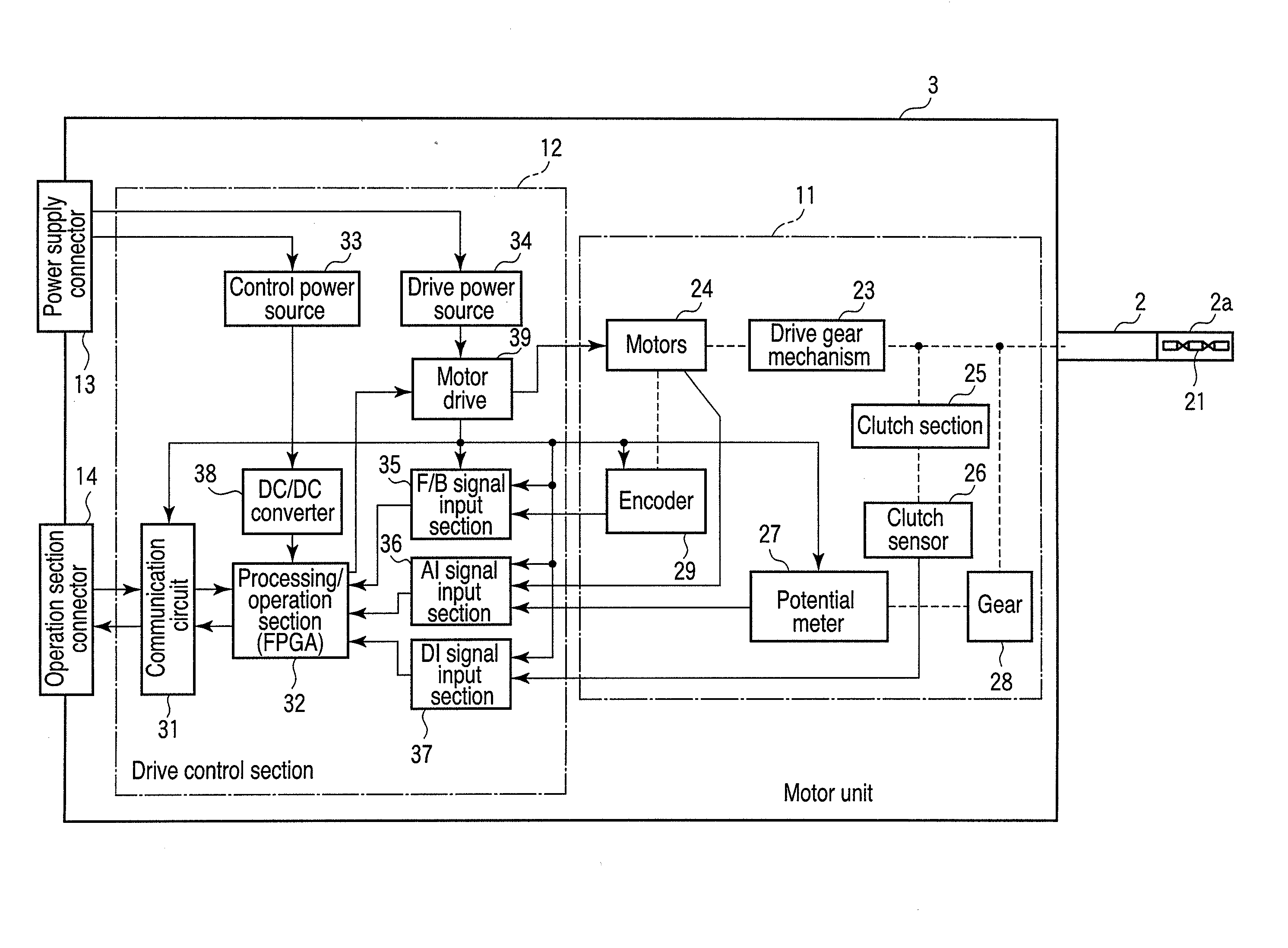
[0026]FIG. 1 is a view showing the internal configuration of a motor unit in a medical control system according to the present invention.

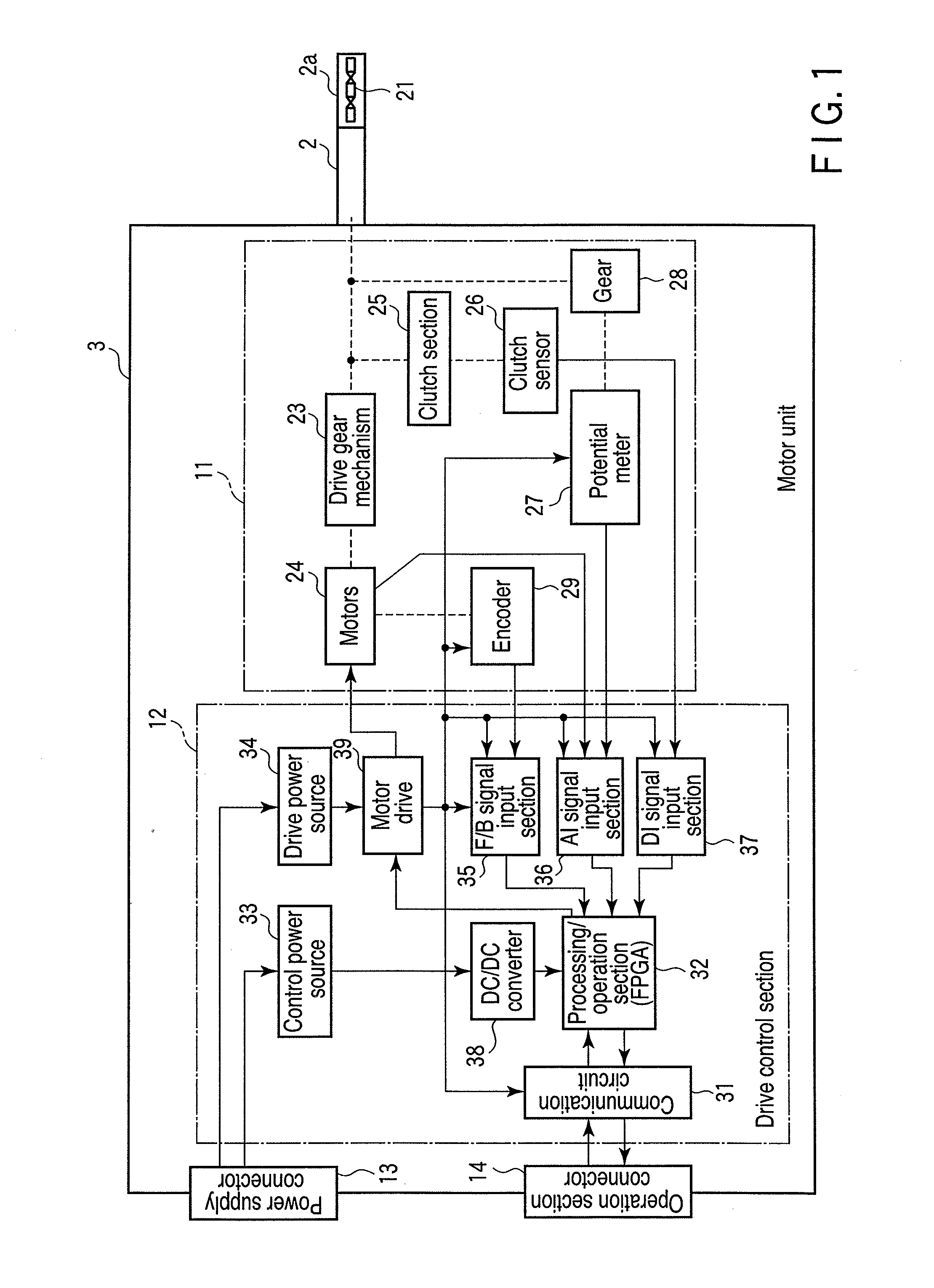
[0027]FIG. 2 is a view showing the schematic overall configuration of the medical control system according to the first embodiment, regarding the following constituent parts of the first embodiment, only those necessary for explanation of the substance of the present invention are shown, it is assumed that constituent parts with which a general endoscopic apparatus is provided, such as a foot switch and the like are provided, and an illustration and description of these constituent parts are omitted.

[0028]A medical control system 1 of this embodiment is a master-slave medical control system configured to carry out a curving operation by means of a plurality of joints provided in an insertion section 2a of an endoscope main body 2 by traction of wires. This medical control system 1 is included a endoscope main body 2 an insertion section [insertion ...

second embodiment

[0056]Next, a second embodiment will be described below.

[0057]In the first embodiment described previously, although the gain of the disturbance characteristics is set high when the motors are in the stopped state, this embodiment is an example in which switching is carried out in such a manner that the frequency range becomes wider in order to enhance the sensitivity of the disturbance characteristics in the stopped state. It should be noted that the configuration of this embodiment is identical with the first embodiment described previously, constituent parts are denoted by using the identical reference symbols, and a description of them will be omitted.

[0058]FIG. 8 is a view showing a relationship between gain and frequency in a controller 40 of this embodiment, and shows a state where the follow-up characteristics and disturbance characteristics are switched.

[0059]In this embodiment too, the transfer from the instruction value [1] to the target position [2] of the motors is iden...

third embodiment

[0065]Next, a third embodiment will be described below.

[0066]In the first and second embodiments described previously, although switching of the gain has been carried out when the motors are in the stopped state or when the operational state is switched, this embodiment is configured in such a manner that when the motors are in the stopped state, in addition to rewriting of the gain, a compensation element (FB) is inserted into the feedback loop by switching.

[0067]FIG. 9 is a view showing the configuration obtained by simplifying the signal processing of a motor drive system. FIG. 10 is a view showing the follow-up characteristics and disturbance characteristics in a controller of this embodiment.

[0068]This embodiment is a configuration example in which in addition to the aforementioned controller (C) 40 and motors (P) 26, a compensation element (FB) 51 and changeover switch 52 are arranged in the feedback loop from the motors (P) 26 to the controller (C) 40. The compensation elemen...


PUM


Abstract

In a medical control system, when motors are in a stopped state according to the determination based on an amount of change in an instruction value, the disturbance characteristics is set at high sensitivity in order to keep the detection capability of a disturbance observer section in an enhanced state during a period to the drive start time of the motors, and when the motors are brought into an operating state, a gain of a controller is returned to a normal setting value to maintain the excellent follow-up characteristics.

Description

CROSS-REFERENCE TO RELATED APPLICATIONS[0001]This is a Continuation Application of PCT Application No. PCT / JP2010 / 059955, filed Jun. 11, 2010, which was published under PCT Article 21(2) in Japanese.[0002]This application is based upon and claims the benefit of priority from prior Japanese Patent Application No. 2009-140167, filed Jun. 11, 2009, the entire contents of which are incorporated herein by reference.BACKGROUND OF THE INVENTION[0003]1. Field of the Invention[0004]The present invention relates to a medical control system used as a treatment tool inserted into a body cavity, and configured to acquire image information on an affected part to be medically treated or provide medical treatment.[0005]2. Description of the Related Art[0006]In general, an endoscopic apparatus inserted into a body cavity, and configured to be used to observe an affected part or the like is known. An insertion section of the endoscopic apparatus to be inserted into the body cavity is configured in su...

Claims


Application Information

Patent Timeline
IPC IPC(8): A61B1/00
CPCA61B1/0052A61B1/0016G05B13/044G02B23/2476
Inventor KAWAI, TOSHIMASA
Owner OLYMPUS CORP
Why Eureka
Try Eureka