Intake air heating and exhaust cooling

a technology of intake air and cooling air, which is applied in the direction of combustion-air/fuel-air treatment, air intakes for fuel, machines/engines, etc., can solve the problems of limiting the amount of heat that can be provided to the engine inlet air and limiting the portion of the trip time, so as to reduce the loss of pumping and accelerate the engine warm-up

Active Publication Date: 2011-06-16
FORD GLOBAL TECH LLC
View PDF10 Cites 25 Cited by
  • Summary
  • Abstract
  • Description
  • Claims
  • Application Information

AI Technical Summary

Benefits of technology

[0002]Heated intake air has been shown to provide a fuel economy benefit (e.g., 1.6%) from reduced pumping losses, and may also provide faster engine warm-up. In one approach, this may be accomplished via coolant heating of engine intake air. In such a case, intake air may be warmed via an exhaust gas recirculation (EGR) cooler.
[0003]The inventors of the present application have recognized a problem in such previous solutions. First, the maximum coolant temperature (e.g., 230° F.) may limit the amount of heat that can be provided to the engine inlet air. Second, the relatively slow warm-up of the coolant may limit the portion of the trip time that may be utilized to heat intake air.
[0004]Accordingly, in one example, some of the above issues may be addressed by intake air heating and exhaust cooling, wherein a double wall exhaust manifold may be configured as an exhaust-to-air heat exchanger. When the intake manifold pressure is less than ambient pressure, the engine can benefit from heated intake air. In such a case, fresh air may be drawn through an interstitial space of a double wall exhaust manifold to heat the air, and then the heated air may be directed to an intake manifold. As such, heated air is sourced to the intake manifold for intake stroke pumping benefit. In this way, by increasing the air heating with the hotter-than-coolant exhaust surfaces, the fuel economy benefit can be further enhanced. Moreover, ample exhaust heat is typically available in less than one minute after start, compared to three minutes or more for coolant heat.
[0005]Further, the inventors of the present application have recognized that the double wall exhaust manifold may additionally serve as an exhaust manifold cooler, by routing excess boost air through the interstitial air space, to cool the exhaust manifold during high load operation. As such, liquid cooling via an integrated exhaust manifold may be eliminated. Such cooling may be beneficial when the intake manifold pressure is greater than ambient pressure and the exhaust temperature is nearing a threshold associated with component durability. In this way, by cooling the exhaust manifold with air derived from excess boost, the fuel economy and emissions penalty of cooling via fuel enrichment can be reduced.
[0006]In this way, the double wall exhaust manifold as described herein establishes a synergy in functionality, in that intake air can be drawn in precisely when intake heating is desired, and the excess boost can push air precisely when exhaust cooling is desired.

Problems solved by technology

First, the maximum coolant temperature (e.g., 230° F.) may limit the amount of heat that can be provided to the engine inlet air.
Second, the relatively slow warm-up of the coolant may limit the portion of the trip time that may be utilized to heat intake air.

Method used


Image

  • Intake air heating and exhaust cooling
  • Intake air heating and exhaust cooling
  • Intake air heating and exhaust cooling

Examples


Embodiment Construction

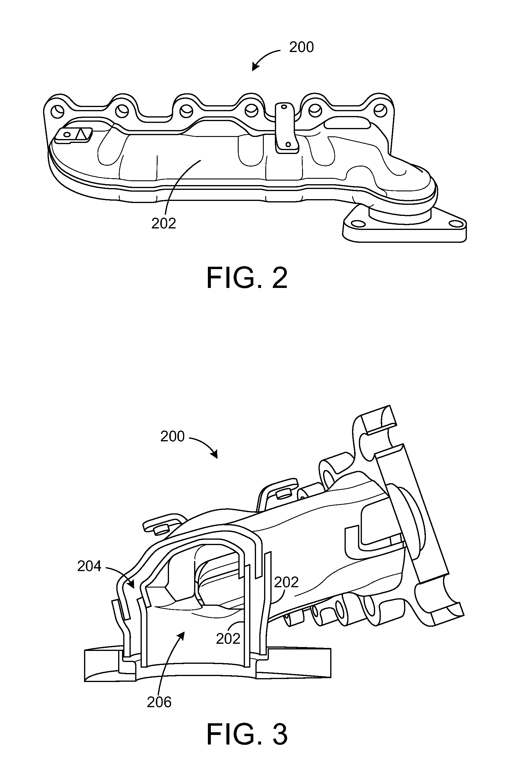
[0014]Embodiments of intake air heating and exhaust cooling are disclosed herein. Such an approach utilizes an interstitial space of a double wall exhaust manifold for heating intake air when the intake manifold pressure is less than ambient pressure and for cooling exhaust gas when the intake manifold pressure is greater than ambient pressure, as described in more detail hereafter.

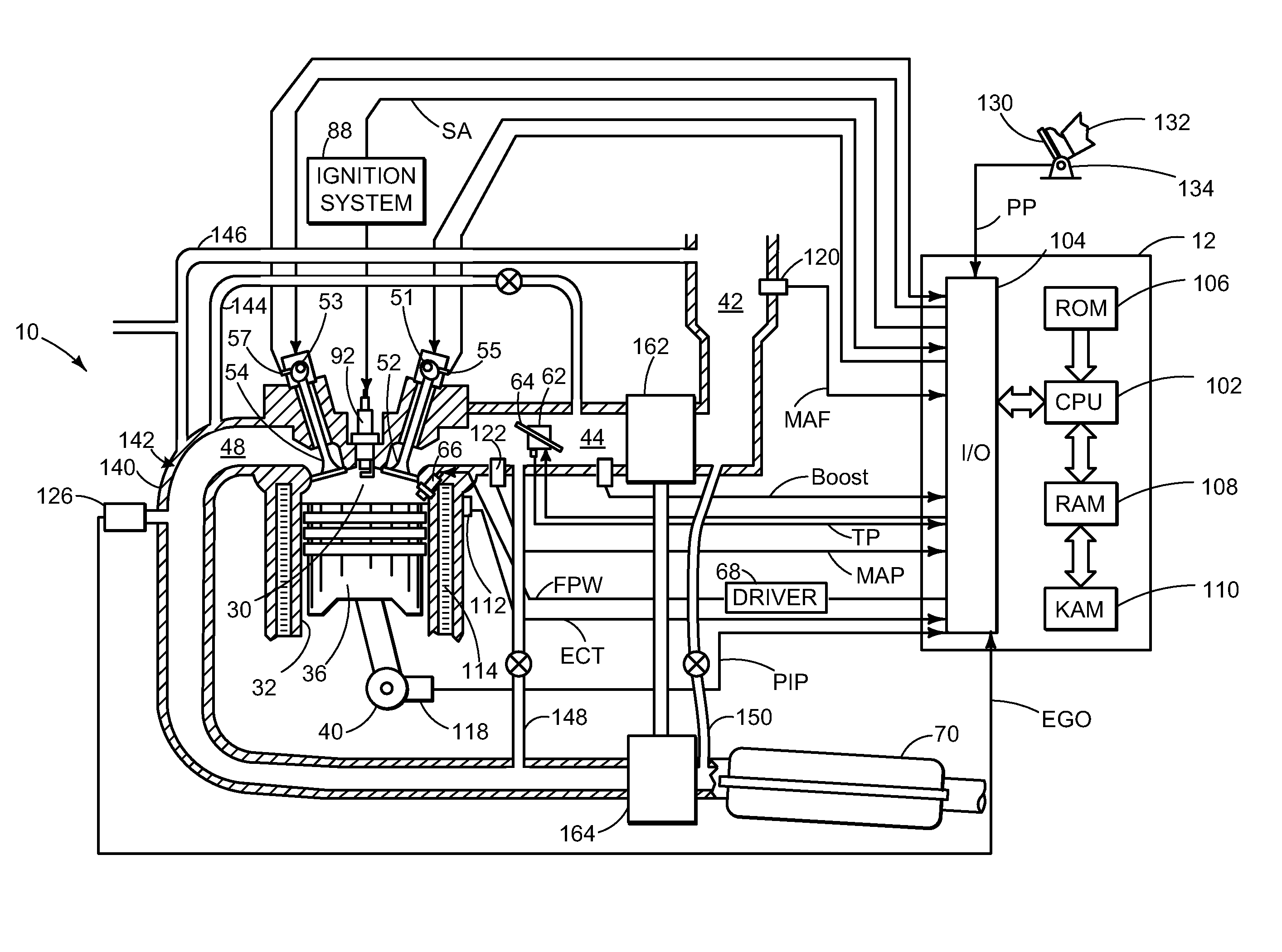
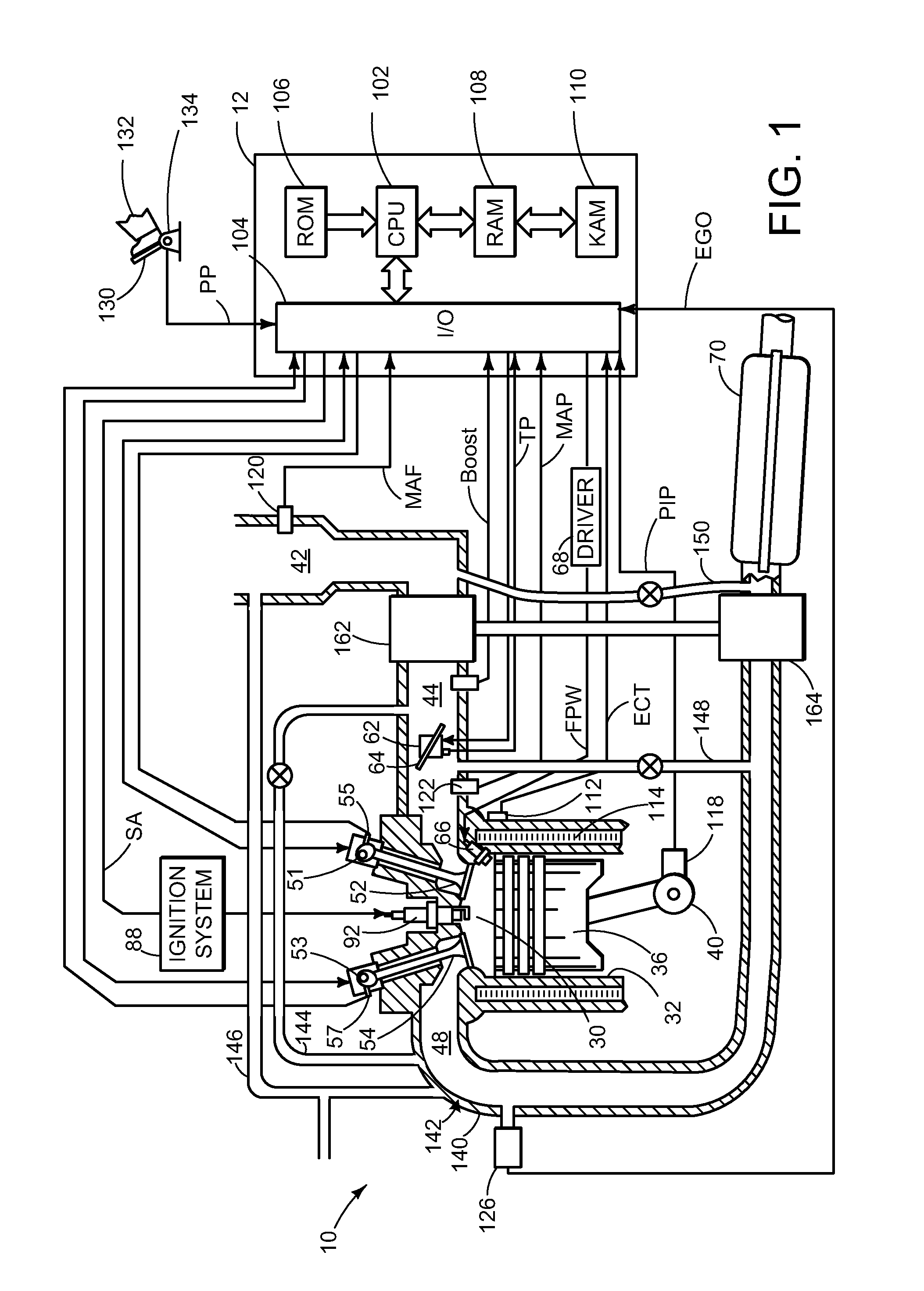
[0015]FIG. 1 is a schematic diagram showing one cylinder of multi-cylinder engine 10, which may be included in a propulsion system of an automobile. Engine 10 may be controlled at least partially by a control system including controller 12 and by input from a vehicle operator 132 via an input device 130. In this example, input device 130 includes an accelerator pedal and a pedal position sensor 134 for generating a proportional pedal position signal PP. Combustion chamber (i.e., cylinder) 30 of engine 10 may include combustion chamber walls 32 with piston 36 positioned therein. Piston 36 may be coupled to...


PUM


Abstract

Intake air heating and exhaust cooling is provided by a double wall exhaust system serving as an exhaust-to-air heat exchanger, sourcing hot air to the intake manifold for intake stroke pumping benefit and cooling the exhaust system during high load operation by routing excess boost air through an interstitial space of the double wall.

Description

TECHNICAL FIELD[0001]The present application relates to intake air heating and exhaust cooling.BACKGROUND AND SUMMARY[0002]Heated intake air has been shown to provide a fuel economy benefit (e.g., 1.6%) from reduced pumping losses, and may also provide faster engine warm-up. In one approach, this may be accomplished via coolant heating of engine intake air. In such a case, intake air may be warmed via an exhaust gas recirculation (EGR) cooler.[0003]The inventors of the present application have recognized a problem in such previous solutions. First, the maximum coolant temperature (e.g., 230° F.) may limit the amount of heat that can be provided to the engine inlet air. Second, the relatively slow warm-up of the coolant may limit the portion of the trip time that may be utilized to heat intake air.[0004]Accordingly, in one example, some of the above issues may be addressed by intake air heating and exhaust cooling, wherein a double wall exhaust manifold may be configured as an exhaus...

Claims


Application Information

Patent Timeline
Patent Type & Authority Applications(United States)
IPC IPC(8): F02M35/10F01N3/02F02B33/00
CPCF01N3/055F01N13/10F02B29/0406F02M25/06Y02T10/20F02M25/08F02M31/093Y02T10/121Y02T10/126F02M25/0707F02M26/05Y02T10/12
Inventor PURSIFULL, ROSS DYKSTRALEONE, THOMAS G.
Owner FORD GLOBAL TECH LLC
Why Eureka
Try Eureka