
Fuel delivery module reinforced fuel tank

a fuel tank and fuel delivery module technology, applied in the direction of liquid fuel feeders, machines/engines, feed systems, etc., can solve the problems of reducing the available space for sensors and/or fuel delivery components, reducing the storage volume of fuel tanks, and increasing material costs, so as to reduce the thickness reduce the deformation of the fuel tank, and increase the material cost

Active Publication Date: 2011-06-16
FORD GLOBAL TECH LLC
View PDF18 Cites 50 Cited by
  • Summary
  • Abstract
  • Description
  • Claims
  • Application Information

AI Technical Summary

Benefits of technology

[0003]Pressure and vacuum changes experienced by a fuel tank may increase when sealed evaporation control (EVAP) systems are employed to reduce evaporative emissions and fuel leakage, e.g., in hybrid electric vehicles. For example, fuel tanks may be partially reinforced by increasing thickness of fuel tank walls and / or including structural elements within the fuel tank body in addition to various non supportive components such as sensors and fuel delivery components within the fuel tank body.
[0005]The inventors herein have recognized issues with such approaches. For example, structural elements included inside a fuel tank may reduce fuel storage volume and available space for sensors and / or fuel delivery components, e.g., a fuel delivery module. Additionally, increasing fuel tank wall thickness may lead to higher material costs and greater fuel tank weight, which may lead to lower fuel efficiency in a vehicle, for example.
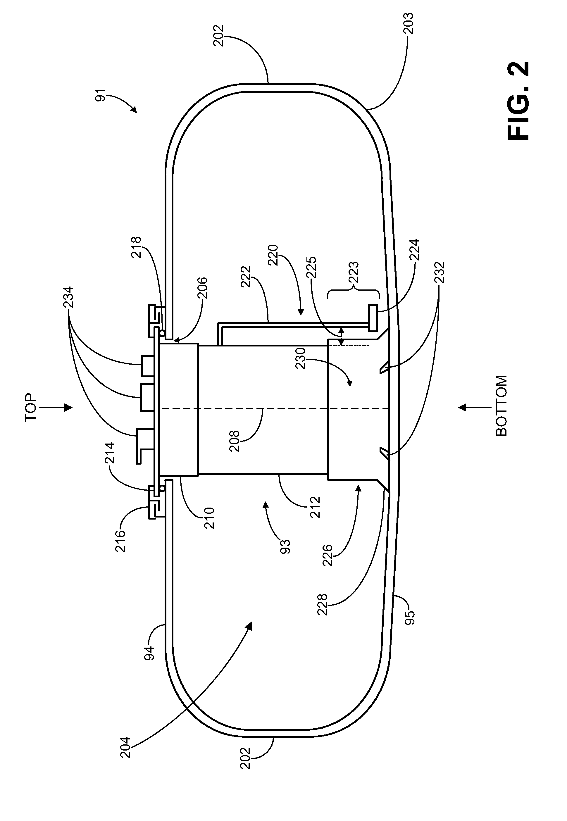
[0007]In this way a fuel tank may be reinforced without the addition of structural elements in the body of the fuel tank which impinge on fuel storage volume and / or lead to higher material costs. Further, fuel tank deformation may be reduced when subjected to pressure and vacuum changes. Additionally, fuel tank wall thickness may be reduced leading to lower material cost and increased fuel efficiency.

Problems solved by technology

Such fuel delivery modules may not provide structural reinforcement to fuel tanks For example, a non-supportive fuel delivery module may include a top flange and bottom cup which are slidably connected, e.g. through sliding steel rods and coil springs, such as described in U.S. Pat. No. 7,159,578.
For example, structural elements included inside a fuel tank may reduce fuel storage volume and available space for sensors and / or fuel delivery components, e.g., a fuel delivery module.
Additionally, increasing fuel tank wall thickness may lead to higher material costs and greater fuel tank weight, which may lead to lower fuel efficiency in a vehicle, for example.
In this way a fuel tank may be reinforced without the addition of structural elements in the body of the fuel tank which impinge on fuel storage volume and / or lead to higher material costs.

Method used


Image

  • Fuel delivery module reinforced fuel tank
  • Fuel delivery module reinforced fuel tank
  • Fuel delivery module reinforced fuel tank

Examples


Embodiment Construction

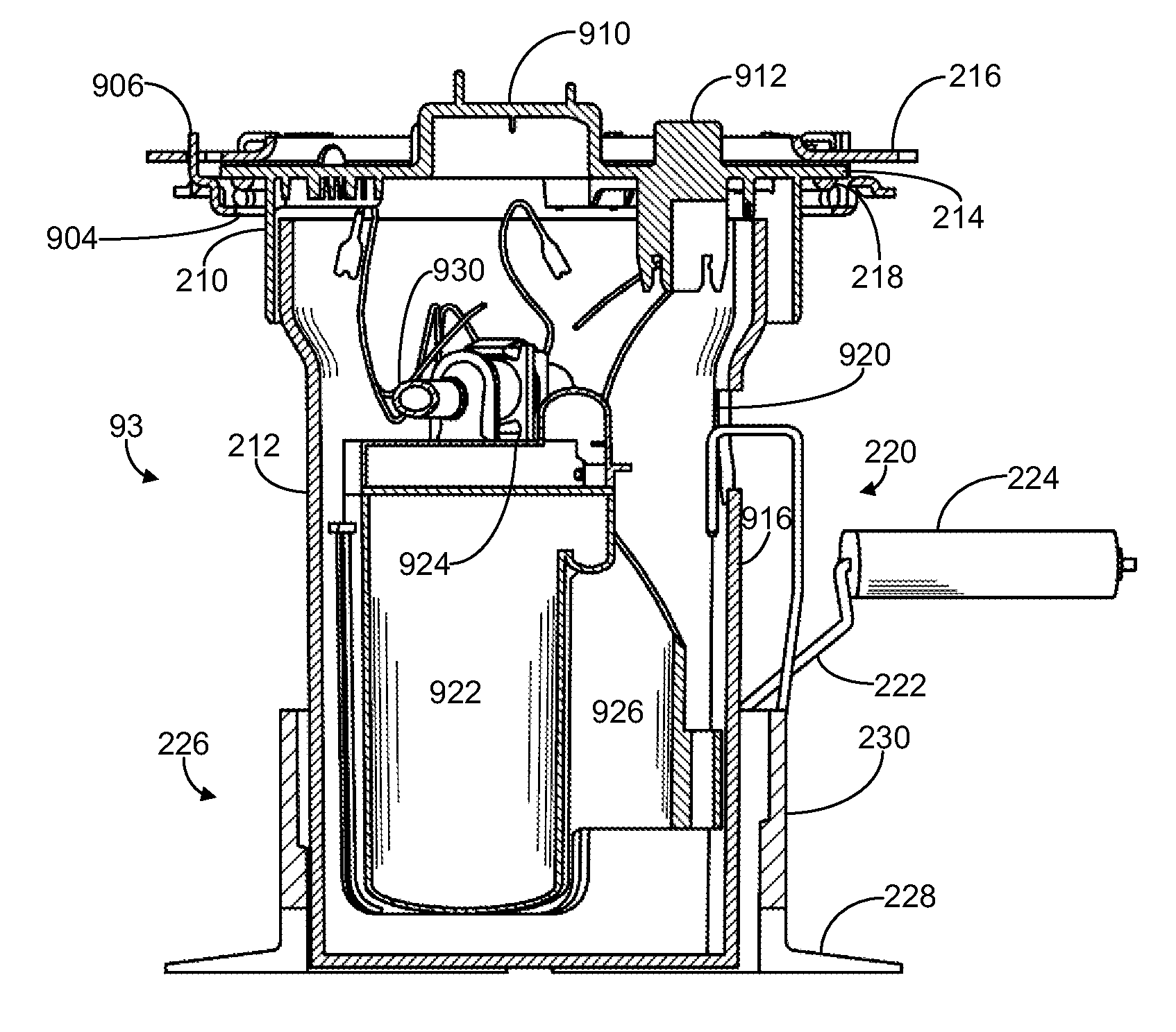
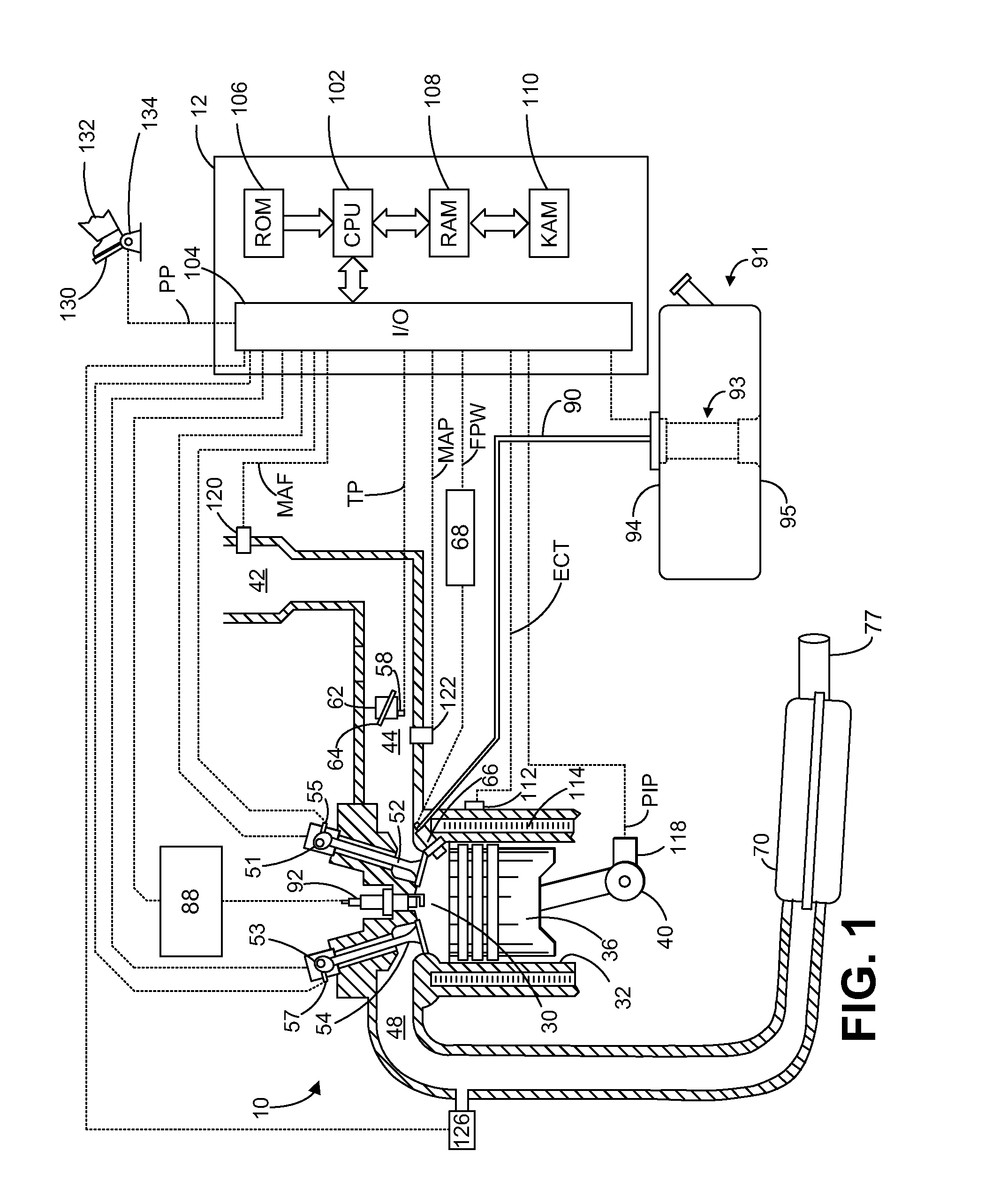
[0018]The following description relates to a fuel tank reinforced with a supportive fuel delivery module (an integrated system that combines a variety of fuel system components into a single module). Such a fuel tank may be used to store fuel for delivery to an engine, such as shown in FIG. 1, e.g., to propel a vehicle.

[0019]FIGS. 2-4 show an example fuel tank including a structurally supportive fuel delivery module (FDM) coupled to outer walls of the fuel tank so as to reduce deflections in the outer walls, e.g., due to pressure and vacuum changes which may occur in the fuel tank.

[0020]A structurally supportive FDM, an example of which is shown in FIGS. 9-12, may include various features to assist in coupling of the FDM to the outer walls of a fuel tank. For example, a retainer coupled to a lower wall of the fuel tank may be configured to lockably receive a base portion of the FDM, e.g., as shown in FIGS. 5 and 6.

[0021]The structurally supportive FDM may be installed and coupled to...


PUM


Abstract

Systems and methods are provided for a structurally supportive fuel delivery module coupled to an upper and lower wall of a fuel tank.

Description

FIELD [0001]The present invention relates to reinforced fuel tanks.BACKGROUND AND SUMMARY [0002]Deflections may occur in fuel tanks due to pressure and vacuum changes, e.g., due to differences between atmospheric pressure around the tank body and the pressure of a gaseous mixture of air and fuel vapor in the fuel tank body. For example, when gas pressure in the tank body exceeds atmospheric pressure, the top of the tank body may expand away from the bottom of the tank body. When atmospheric pressure exceeds the gas pressure in the tank body, the top of the tank body may collapse toward the bottom of the tank body.[0003]Pressure and vacuum changes experienced by a fuel tank may increase when sealed evaporation control (EVAP) systems are employed to reduce evaporative emissions and fuel leakage, e.g., in hybrid electric vehicles. For example, fuel tanks may be partially reinforced by increasing thickness of fuel tank walls and / or including structural elements within the fuel tank body...

Claims


Application Information

Patent Timeline
IPC IPC(8): F02M37/04
CPCF02M37/106F02M37/103
Inventor ZHANG, YILE, DATTHIEL, STEVEN ANTONEBRAWN, BRENT DARRELL
Owner FORD GLOBAL TECH LLC
Learn More