

Method of forming sealed refractory joints in metal-containment vessels, and vessels containing sealed joints
a technology of metal-container vessels and sealing joints, which is applied in the direction of manufacturing converters, furnaces, charge manipulation, etc., can solve the problems of all such joints deteriorating
- Summary
- Abstract
- Description
- Claims
- Application Information
AI Technical Summary
Benefits of technology
Problems solved by technology
Method used
Image

Examples
Embodiment Construction
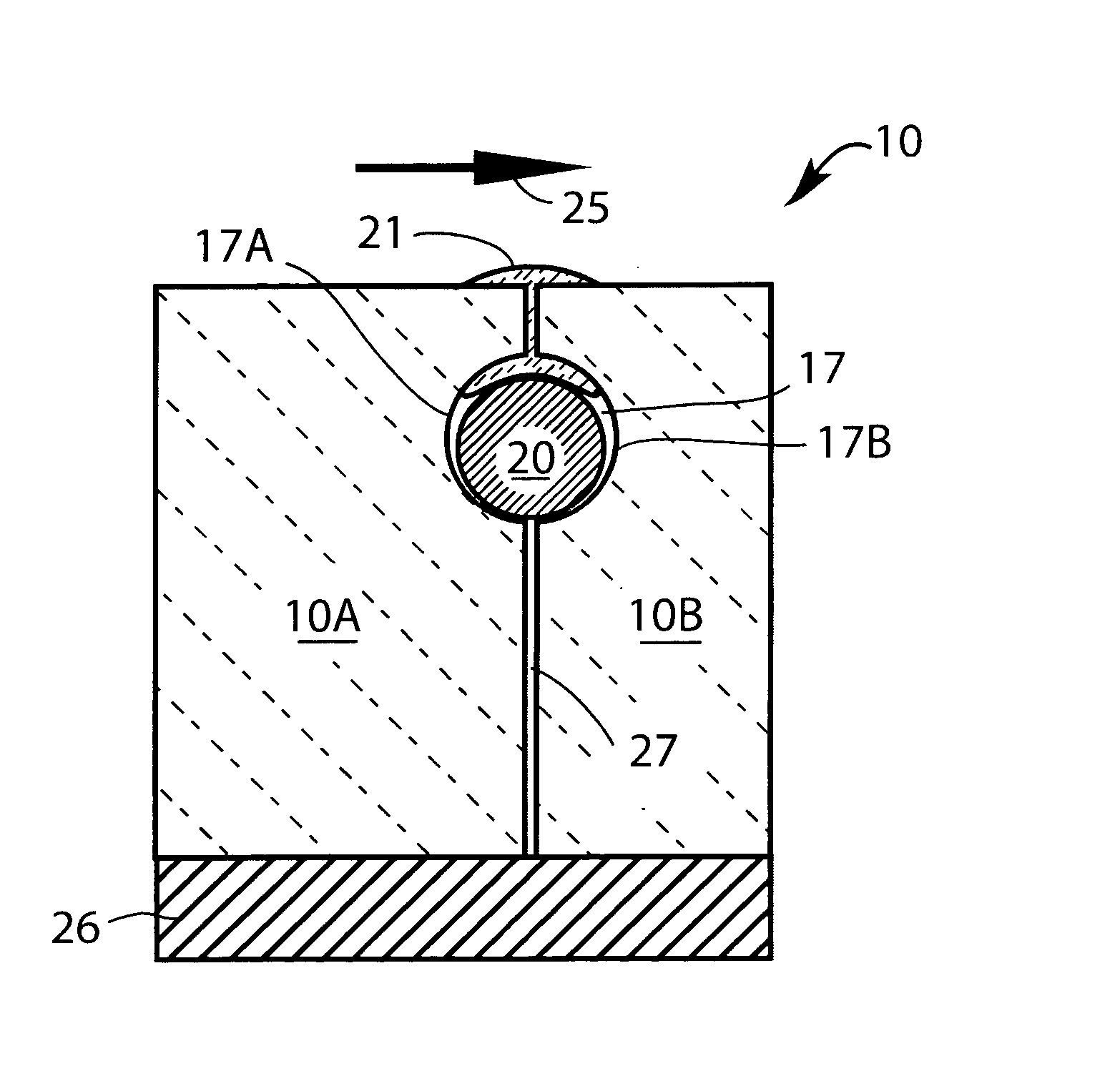
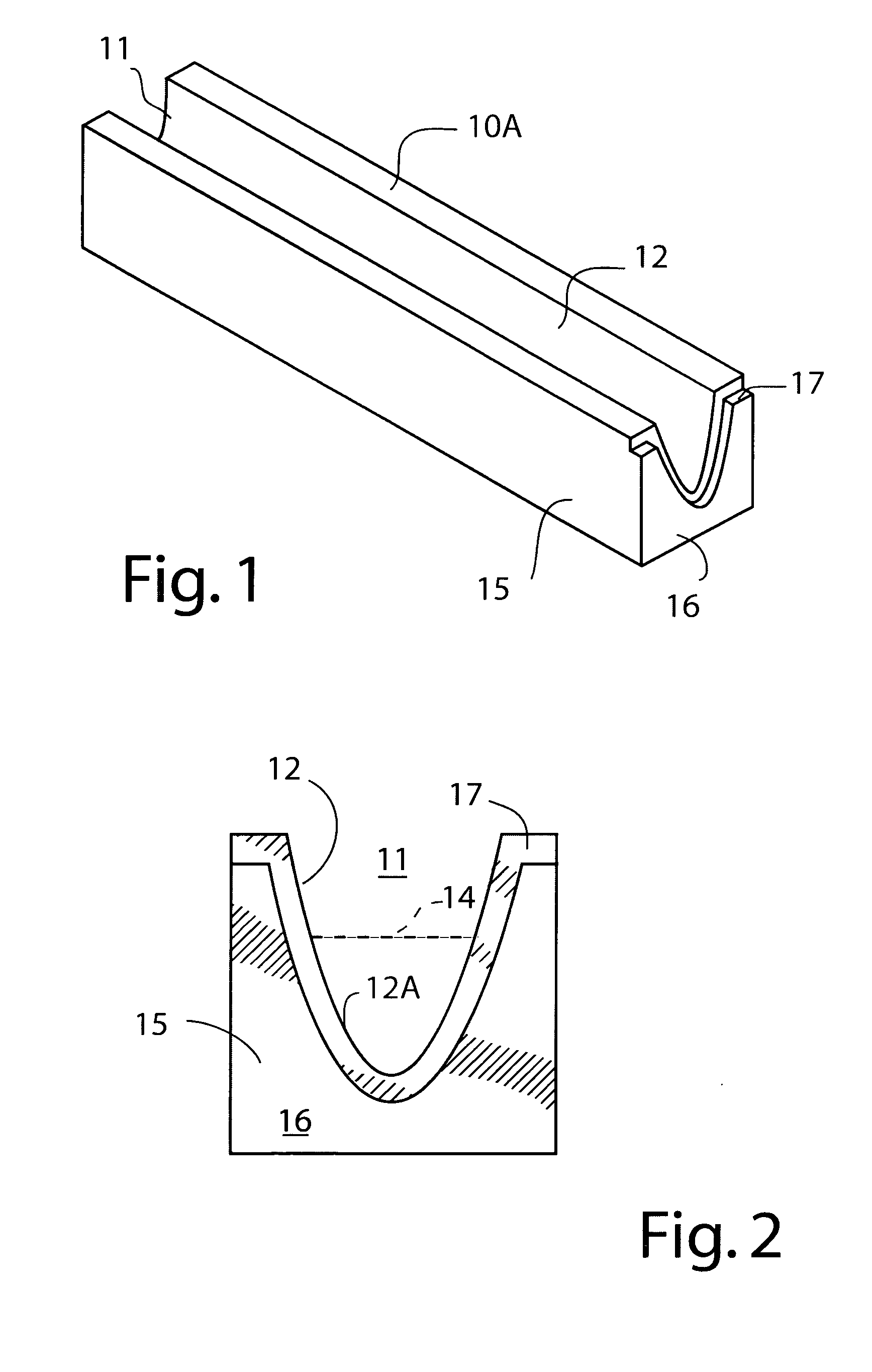
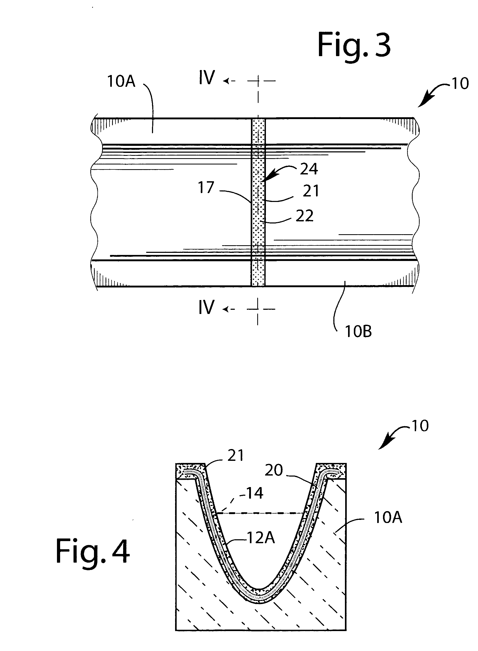
[0008]An exemplary embodiment of the invention provides a method of preparing a reinforced refractory joint between refractory sections of a vessel used for containing or conveying molten metal. The method comprises introducing a mesh body made of metal wires (preferably of a metal that is resistant to attack by the molten metal contained in the vessel) into a gap between metal-contacting surfaces of adjacent refractory sections of the vessel so that the mesh body is positioned beneath the metal-contacting surfaces, and covering the mesh body with a layer of moldable refractory material (preferably in the form of a malleable paste) to seal the gap between the metal-contacting surfaces.
[0009]The mesh body forms a flexible and compressible support for the moldable refractory material. Furthermore, in case the refractory material becomes cracked or broken, the mesh body holds the pieces in place and maintains the joint seal. The mesh body preferably has mesh openings of a size (e.g. 1-...
PUM
| Property | Measurement | Unit |
|---|---|---|
| Size | aaaaa | aaaaa |
| Size | aaaaa | aaaaa |
| Electrical resistance | aaaaa | aaaaa |
Abstract
Description
Claims
Application Information