Image recognition apparatus, and operation determination method and program therefor

a recognition apparatus and image technology, applied in the field of image recognition apparatus and operation determination method, can solve the problems of not being able to identify, user cannot identify, de facto standards, etc., and achieve the effect of lowering the transparency of the indicator, and reducing the distance between the operator and the virtual operation plan

Inactive Publication Date: 2011-06-16
SHIMANE PREFECTURAL GOVERNMENT MATSUE
View PDF3 Cites 130 Cited by
  • Summary
  • Abstract
  • Description
  • Claims
  • Application Information

AI Technical Summary

Benefits of technology

[0028]The invention according to claim 19 is the image recognition apparatus according to claim 16, characterized in that transparency for the indicator is lowered when the distance from the part of the operator to the virtual operation plane is reduced.
[0029]The invention according to claim 20 is the image recognition apparatus according to claim 16, characterized in that the contrast between the indicator and an image to be operated displayed on the image display means is increased when the distance from the part of the operator to the virtual operation plane is reduced.

Problems solved by technology

However, for a conventional operation during which gestures are used, specific standard gestures, such as de facto standards, have not been established, and a user can not identify, at a single glance, the correlation of an action with an available operation, other than one during which the index fingers are used for pointing at XY coordinates.
Therefore, there is a problem that a realistic method is not present whereby an operation, such as clicking or deciding (double click, etc.), is easily and smoothly performed.
Moreover, unlike an input apparatus like a touch panel that an operator can touch directly, it is difficult for a conventional gesture detection apparatus to exactly read the intent of an operator.
Specifically, as a problem, when an operator has moved in a certain way, it is not easy to determine whether the action of the operator indicates input intent, or whether the operator moved simply because of a habit.
As a result, even a simple gesture, for example, can not be identified unless it is performed unnaturally and noticeably, and as another problem, either an advance rule for gestures is required, or the use of complicated gestures is inhibited.

Method used


Image

  • Image recognition apparatus, and operation determination method and program therefor
  • Image recognition apparatus, and operation determination method and program therefor
  • Image recognition apparatus, and operation determination method and program therefor

Examples


first embodiment

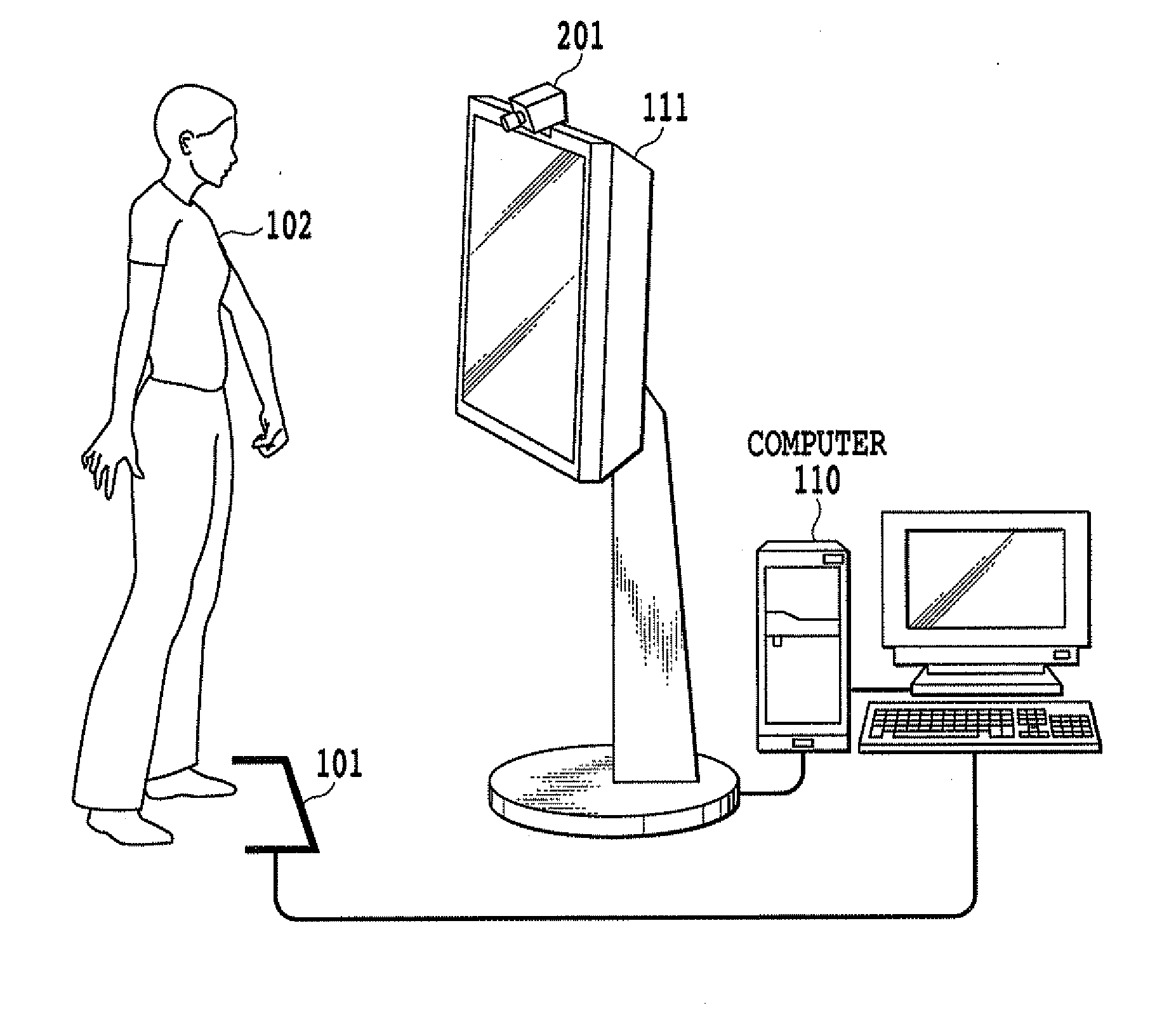
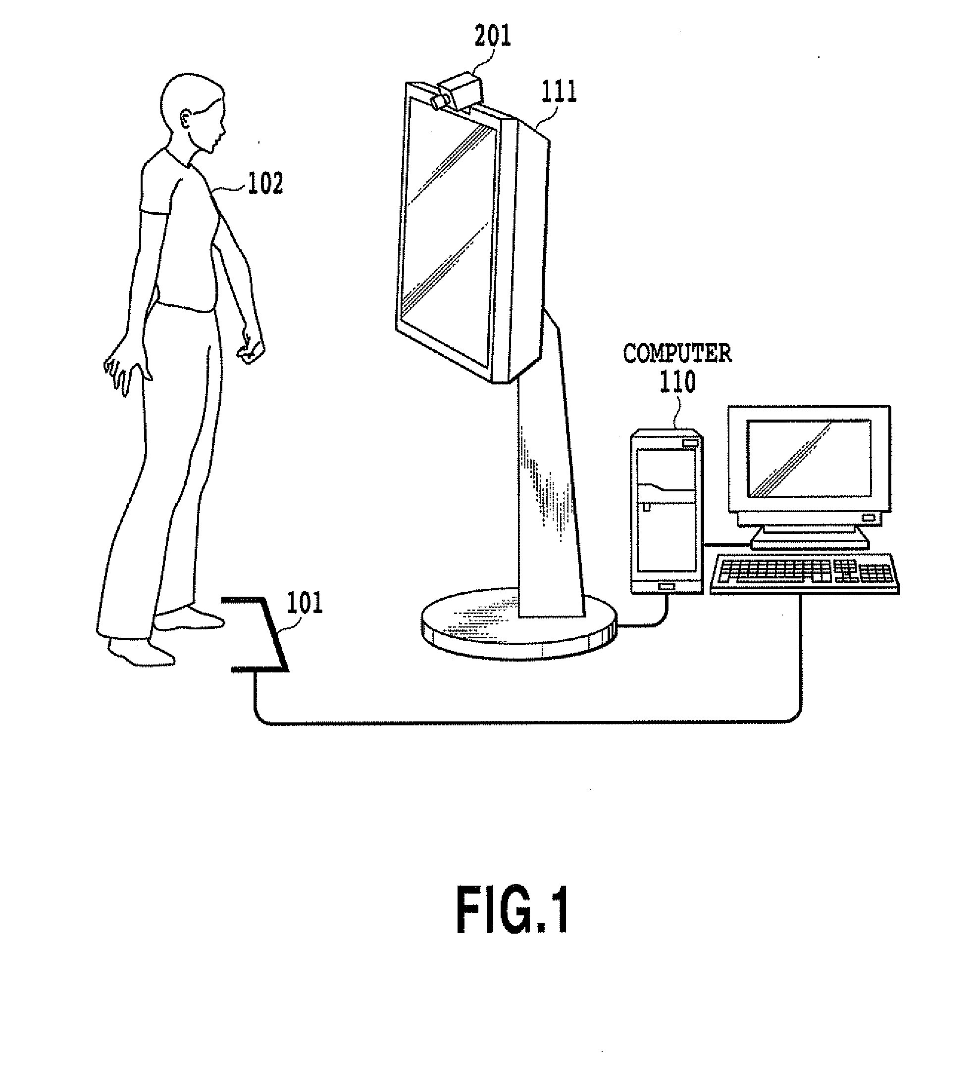
[0080]FIG. 1 is a diagram illustrating an example operation input system wherein a maker 101, which is an operation plane forming reference for this embodiment, is indicated on the surface of a floor. In this embodiment, the marker 101 is located between an operator and a monitor 111, and for operating the operation input system, the operator 102 can keep in mind that the movement or the shape of a portion that is extended over the marker 101 toward the display screen is employed for determination of an operation. Various types of video pictures for various applications that are operating purposes of this system are displayed on the monitor 111. Further, as will be described later, operation input can be supported, i.e., for example, the part of the operator 102 to be determined is displayed at the corner of the screen, and the operator 102 can identify a probable action that is currently determined to be an operation instruction. The action of the operator 102 is filmed by a video ...

second embodiment

[0100]A system configuration for this embodiment is basically the same as that for the first embodiment described above, and is provided based on a more specific usage situation. That is, for this embodiment, while taking the system and the processing in the first embodiment into account, markers 1902 and 1903 are provided for a predetermined solid object, such as a desk-like solid item 1901 shown in FIG. 21, and are employed as operation plane forming references to form a virtual operation plane 701, and when a finger 601, etc., is used to manipulate the virtual operation plane, operation input is enabled. An explanation for this embodiment will be given by employing a table in a living room as an example solid object, and by assuming a case wherein an operator is seated on a sofa at home, etc., while manipulating the system. However, the item in use is not limited to this, and various other items for individual use, such as a platform for a speaker, a stand and a guard like a bar ...

third embodiment

[0106]A system configuration for this embodiment is basically the same as that for the first embodiment described above, and differs from that for the second embodiment based on a specific usage situation. That is, for this embodiment, unlike the second embodiment, assume a case wherein, for example, manipulation is performed while lying in a bed in a hospital, as shown in FIG. 11. Here, it is assumed that a monitor 111 is, for example, a television located in a ward.

[0107]In this embodiment, a marker 1101 and auxiliary markers 1103 designated on a bed table 1102 are employed as operation plane forming references, and based on these markers, an operator 102 who manipulates a television by slightly raising his or her body from a bed, assumes that an operation plane 701 is formed above the marker 1101, and performs various acts to access the operation plane in order to perform a desired operation. Specifically, as shown in FIG. 12, the operator 102 sticks a finger of the marker 1101 o...


PUM


Abstract

An image for an operator is extracted, and an operation determination unit employs a relationship, relative to a marker of an operation input system, for the operator, who is standing behind the marker when viewed by a video camera. When a body part of the operator comes to the front of an operation plane, as viewed by the video camera, the operation determination unit determines that an action for an input operation has been started, and examines the shape and the movement of each individual body part (an open hand, two fingers that are being held up, etc.), and determines whether the shape or the movement is correlated with one of operations that are assumed in advance.

Description

TECHNICAL FIELD[0001]The present invention relates to an image recognition apparatus and an operation determination method, and more particularly, to an image recognition apparatus and an operation determination method for employing an image or images recorded by a video camera, etc., to determine an action that is measured.BACKGROUND ART[0002]Recently, various apparatuses and methods have been proposed for use as interfaces between computers, or other electronic equipment, and human operators, i.e., man-machine interfaces, and, especially for game machines and operation guidance apparatuses, techniques have been proposed according to which, to ensure the performance of an operation, a full image of the figure of an operator, or a partial image of the figure is recorded by a camera, and the intent of the operator is determined based on either recorded image type. Further, an example technique proposed in Japanese Patent Laid-Open No. 2004-78977, includes the use of a host computer f...

Claims


Application Information

Patent Timeline
Patent Type & Authority Applications(United States)
IPC IPC(8): G09G5/00H04N13/00A63F13/219G06F3/01G06T1/00G06T7/00
CPCA63F13/04A63F2300/1068G06F3/0304A63F2300/6045G06F3/017A63F2300/1093A63F13/497A63F13/57A63F13/42A63F2300/64A63F2300/634G06F3/0346A63F13/219A63F13/537A63F13/428A63F13/213
Inventor IZUMI, KENJI
Owner SHIMANE PREFECTURAL GOVERNMENT MATSUE
Why Eureka
Try Eureka