Photocatalyst coating composition
a coating composition and photocatalyst technology, applied in the direction of organic compound/hydride/coordination complex catalyst, physical/chemical process catalyst, coating, etc., can solve the problems of reducing the drying time after applying the photocatalyst coating composition, deteriorating the coating composition, and reducing the durability of the use of organic resin binder, so as to achieve high binding energy, prevent self-collapse of the coating film, and high function
- Summary
- Abstract
- Description
- Claims
- Application Information
AI Technical Summary
Benefits of technology
Problems solved by technology
Method used
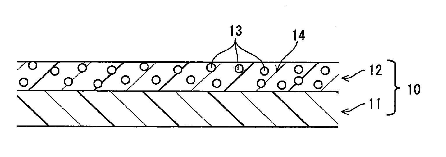
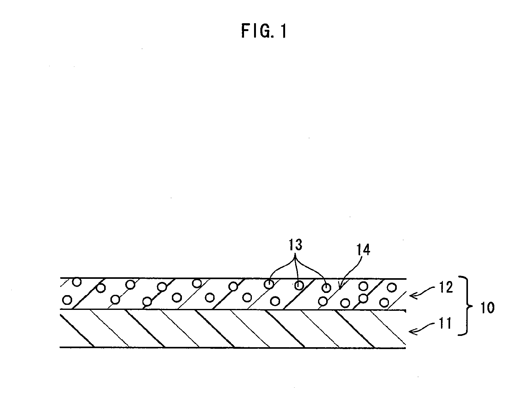
Image

Examples
experiment 1
(Experiment 1)
[0075]Experiments for adhesion property and abrasion resistance were conducted, regarding the case where a substrate was made from stone material. A fluororesin used in the present invention was in the form of an aqueous emulsion.
example a1
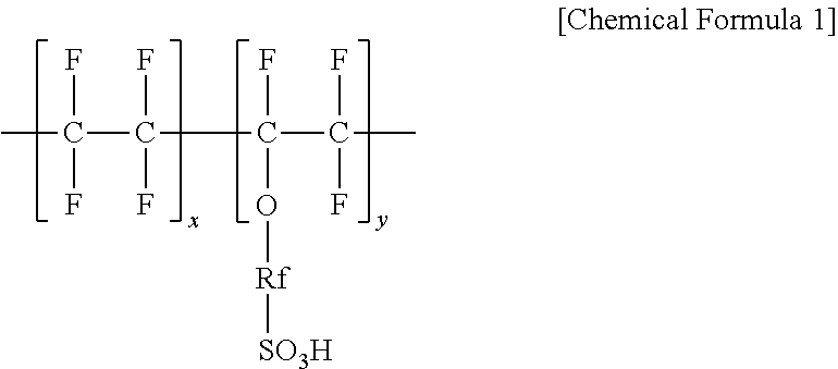
[0076]35 pts.wt. of 20 percent solution of “Nafion DE 2021” manufactured by E. I. du Pont de Nemours and Company (prepared by Wako Pure Chemical Industries, Ltd.), 3 pts.wt. of “ST-01” (manufactured by Ishihara Sangyo Kaisha, Ltd.: absorption surface area of 300 m2 / g), which is titanium oxide of porous photocatalyst particles, and 42 pts.wt. of isopropyl alcohol were blended. The blend was vigorously agitated by using a paint shaker. Additionally, 20 pts.wt. of “LUMIFLON FE 4400” (manufactured by ASAHI GLASS CO., LTD.), which is an aqueous emulsion of trifluorochloroethylene-alkyl vinyl ether copolymer, was added to the blend, and the blend was agitated well. A photocatalyst coating composition that is an example of the present invention (Example A1) was formed by this process.
experiment 2
(Experiment 2)
[0085]Next, regarding the case where a substrate is made of tent fabric composed of a fluororesin (PVDF), experiments for adhesion property and abrasion resistance of a coating film were conducted. The fluororesin in a particle state was used in the present experiment.
PUM
| Property | Measurement | Unit |
|---|---|---|
| Time | aaaaa | aaaaa |
| Composition | aaaaa | aaaaa |
| Photocatalytic properties | aaaaa | aaaaa |
Abstract
Description
Claims
Application Information