Magnetic microstructures for magnetic resonance imaging
a magnetic resonance imaging and magnetic microstructure technology, applied in the field of magnetic resonance identity systems, magnetic resonance imaging contrast agents and spectroscopic agents, can solve problems such as obscuring the distinction between
- Summary
- Abstract
- Description
- Claims
- Application Information
AI Technical Summary
Problems solved by technology
Method used
Image

Examples
example 1
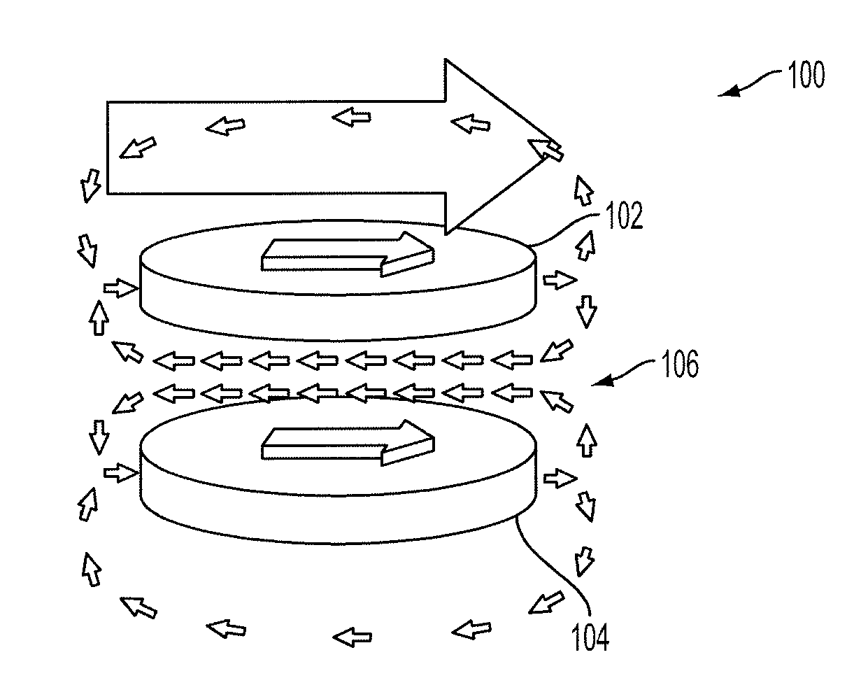
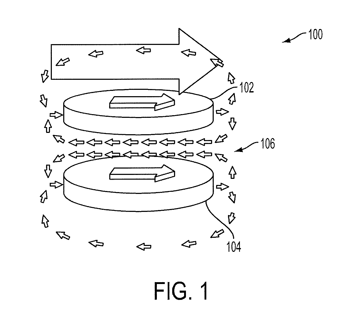
[0089]Among several possible configurations according to various embodiments of the current invention, we demonstrate a spaced, magnetizable double-disc geometry (see FIGS. 1, 2 and 6-10) because in addition to generating a highly homogeneous field over a large volume fraction, its open design helps maximize water self-diffusion that, as discussed later, dramatically increases its signal-to-noise ratio (SNR) over that of any closed structure.
[0090]The double-disc geometry of this example is also inherently scalable and well-suited to massively parallel wafer-level microfabrication. Particle complexes can be surface micromachined in various different ways that may, for example, include various combinations of metal evaporation, sputtering, and electroplating depositions together with various wet and dry etching processes. The discs are separated via non-magnetic spacers: either an internal metal post that remains after a timed etch, or external lithographically-defined bio-compatible...
example 2
[0107]In this example according to some embodiments of the current invention, we consider a simple, yet generalizable, resputtering technique on top-down photolithographically prepatterned substrates. Often regarded as an undesirable by-product of ion milling, redeposited back-sputtered material is here instead exploited to yield scalable, large-area, parallel fabrication of accurately defined free-standing nanostructures. Demonstrating the added functionality that such top-down definition can permit, a new form of MRI label is introduced: cylindrical magnetic nanoshells that can function both as conventional T2* and as new spectral-shifting, or “color”, contrast agents. These labels, which are hollow cylinders formed from nanometers-thick shells of magnetizable material, can both modulate local magnetic resonance relaxivities as well as generate controlled, tunable nuclear magnetic resonance (NMR) shifts in the surrounding water through precise control of the shell heights, radii a...
example 3
[0125]FIG. 25 is a schematic illustration of a magnetic resonance structure according to another embodiment of the current invention. In this case, a thin ring-like magnetizable structure (shown in wire-frame view, but intended to represent a solid ring of material) surrounds or is attached to the inside walls of a stent, for example. The ring could also be replaced with a pair of two magnetizable elements on opposite sides of the stent (FIG. 26) or with multiple pairs of magnetizable elements at the same longitudinal position along the stent but rotated around the stent axis by different angles, where each pair consists of one piece on each opposite side of the stent. In other embodiments, there can be so many pairs arrayed around at different angles that combined they effectively add up to approximately the ring structure again. The geometry that is more favorable may depend on the type of stent (i.e., whether it is intended to be expandable via a catheter balloon or not. The spec...
PUM
 Abstract
Description
Claims
Application Information
 - R&D
- Intellectual Property
- Life Sciences
- Materials
- Tech Scout
- Unparalleled Data Quality
- Higher Quality Content
- 60% Fewer Hallucinations
Browse by: Latest US Patents, China's latest patents, Technical Efficacy Thesaurus, Application Domain, Technology Topic, Popular Technical Reports.
© 2025 PatSnap. All rights reserved.Legal|Privacy policy|Modern Slavery Act Transparency Statement|Sitemap|About US| Contact US: help@patsnap.com