
Method of operating an auxiliary electric pump

a technology hydraulic system, which is applied in the direction of vehicle position/course/altitude control, process and machine control, instruments, etc., can solve the problems of auxiliary electric pump not being designed, energy loss with corresponding adverse effects on the efficiency of hydraulic system and transmission, and construction effort and cost, so as to limit the loading of electric auxiliary pump

Inactive Publication Date: 2011-06-16
ZF FRIEDRICHSHAFEN AG
View PDF12 Cites 36 Cited by
  • Summary
  • Abstract
  • Description
  • Claims
  • Application Information

AI Technical Summary

Benefits of technology

[0009]This has the advantage that limiting of the load of the electric auxiliary pump takes place by virtue of existing elements so that, compared with the prior art, a pressure-relief valve and the associated structural space requirement and costs can be omitted. Furthermore, the loading of the electric auxiliary pump can be varied to suit the situation.
[0014]Furthermore, to limit the loading of the electric auxiliary pump the electronic control unit can limit the time for which the electric auxiliary pump is switched on and hence the time for which it is loaded. In this way it is advantageously possible for the electric auxiliary pump to build up a system pressure higher than the defined pressure limit value for a short time, if this is required by the operating function concerned. The switch-on duration is chosen taking into account the value of the system pressure.
[0015]Moreover, it is possible to limit both the switch-on duration of the electric auxiliary pump and the system pressure, this depending on the operating function selected.
[0017]According to a further development of the invention it can be provided that during a first operating function the electronic control unit switches off the electric auxiliary pump if the system pressure rises above the defined pressure limit value because of a frictional defect in the control of the system pressure valve. Thus, in contrast to the prior art, a defect situation can be recognized by detecting the system pressure, and switching the electric auxiliary pump on can be prevented.
[0020]Alternatively, for the second operating function, the permissible switched-on duration of the electric auxiliary pump can be determined in the electronic control unit from a characteristic curve stored therein, in which a maximum switched-on duration is associated with the value of the system pressure. This advantageously makes it possible, depending on the requirements of the various operating functions, to increase the level of the system pressure with an adapted switched-on duration.

Problems solved by technology

This peak demand must be covered by the delivery characteristic of the pump, and consequently, other than during the operating functions, the volume flow delivered exceeds the needs of the automatic transmission and thus, in combination with the pressure produced, constitutes an energy loss with corresponding adverse impacts on the efficiency of the hydraulic system and the transmission.
To keep down the construction effort and costs, the auxiliary electric pump is not designed for the maximum peak pressures that occur in the hydraulic system.
The disadvantages of this solution are the structural space required in the transmission for fitting the pressure-relief valve in the hydraulic system, the additional components and the costs for the pressure-relief valve.

Method used


Image

  • Method of operating an auxiliary electric pump
  • Method of operating an auxiliary electric pump
  • Method of operating an auxiliary electric pump

Examples


Embodiment Construction

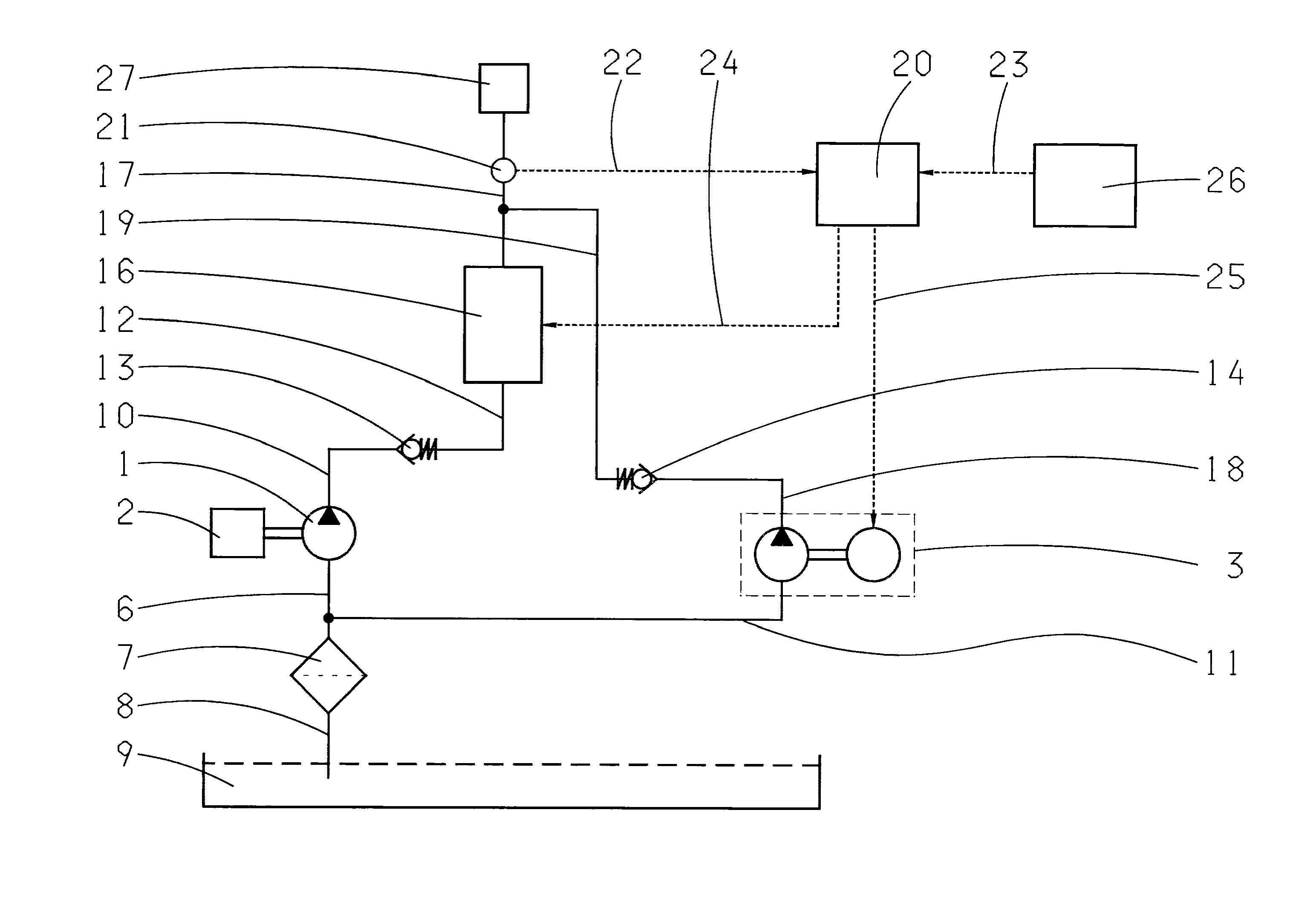
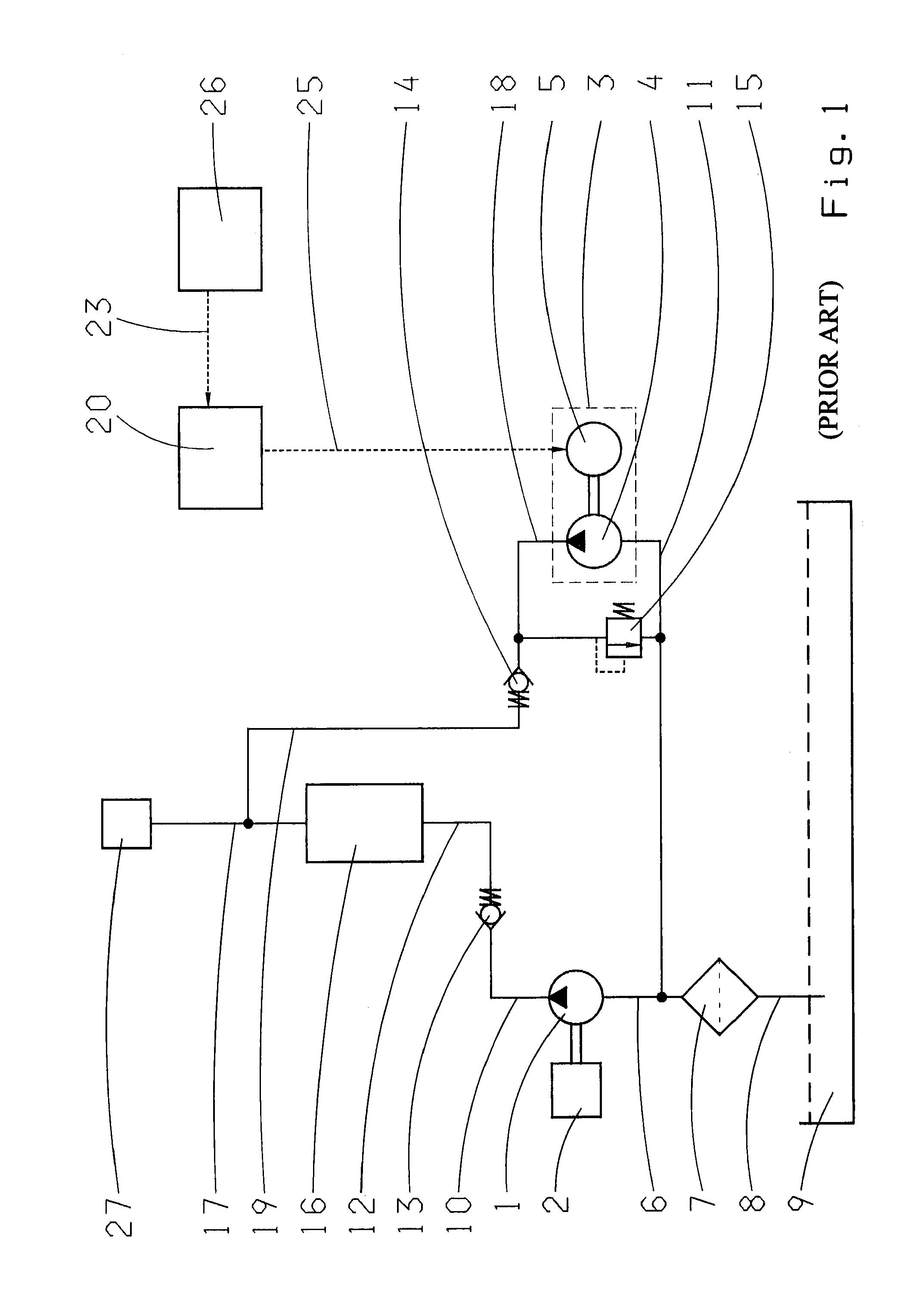
[0027]FIG. 1 shows a hydraulic system of an automatic transmission according to the prior art. The hydraulic system comprises a main pump 1 and an electric auxiliary pump 3. The main pump 1 is driven mechanically by an internal combustion engine 2, which serves to drive the vehicle. Alternatively an electric motor would also be conceivable for driving the vehicle, or a combination of both types of motor. The main pump 1 can be in the form of a displacement pump, in particular a gearwheel pump. Of the possible design forms of a gearwheel pump as an inner or outer gearwheel pump, in an automatic transmission the use of an inner gearwheel pump is preferred because of its compact structure. The electric auxiliary pump 3 comprises a pump 4 and an electric motor 5 that drives it, the pump 4 also preferably being in the form of a displacement pump.

[0028]The main pump 1 draws up an operating medium stored in the transmission sump 9, preferably oil, through a suction line 6, a filter 7 and a...


PUM


Abstract

A method for operating a hydraulic system of an automatic transmission, in particular in a hybrid drivetrain, in which the hydraulic system comprises a main pump that is powered by an internal combustion engine and / or an electric drive motor, an electric auxiliary pump and a system pressure valve for setting a system pressure, to ensure various operating functions. In addition to the main pump, the electric auxiliary pump also supplies the hydraulic system with a volume flow of an operating medium. The loading of the electric auxiliary pump is determined in an electronic control unit with regard to the value of the system pressure and the loading of the electric auxiliary pump is limited, by the electronic control unit, with regard to the selected operating function.

Description

[0001]This application claims priority from German patent application serial no. 10 2009 054 754.1 filed Dec. 16, 2009.FIELD OF THE INVENTION[0002]The invention concerns a method for operating a hydraulic system of an automatic transmission, in particular in a hybrid drivetrain.BACKGROUND OF THE INVENTION[0003]In automatic transmissions the shifting of the various gear ratio steps generally takes place by hydraulic pressurization of shift elements such as clutches or brakes. The shift elements, together with an oil supply system, form a hydraulic system. To change the gear ratio, certain shift elements in the hydraulic system are relieved from hydraulic pressure and other shift elements are filled with an operating medium and acted upon by a hydraulic pressure. Since the gear ratio change has to be completed within a finite, limited time, the filling of the shift elements must take place correspondingly quickly, and this entails producing a high volume flow in the hydraulic system. ...

Claims


Application Information

Patent Timeline
IPC IPC(8): F16H61/02G06F19/00
CPCB60W10/30B60W20/00F16H61/0031Y10T477/6939Y10T477/69393Y10T477/60F16H2059/683B60W20/10
Inventor ZOLLNER, TOBIASALLGAIER, BERNDSCHWEMER, CHRISTIAN
Owner ZF FRIEDRICHSHAFEN AG
Features
  • Generate Ideas
  • Intellectual Property
  • Life Sciences
  • Materials
  • Tech Scout
  • Unparalleled Data Quality
  • Higher Quality Content
  • 60% Fewer Hallucinations
Learn More