Radiation measuring device and diagnostic method thereof

a technology of measuring device and measuring device, which is applied in the direction of optical radiation measurement, instruments, nuclear elements, etc., can solve the problems of inability to improve diagnostic accuracy, difficult to bring the captured pulse train of the up/down counter into coincidence with the captured pulse train of the pulse height analyzer, etc., and achieve high-accurate self-diagnosis and simple configuration

Active Publication Date: 2011-06-16
MITSUBISHI ELECTRIC CORP
View PDF4 Cites 19 Cited by
  • Summary
  • Abstract
  • Description
  • Claims
  • Application Information

AI Technical Summary

Benefits of technology

[0007]The invention was devised to solve the problems discussed above and has an object to provide a radiation measuring device of a simple configuration that enables a high-accurate self-diagnosis online on the count rate measurement that is the keystone of the radiation measurement and a diagnostic method thereof.
[0010]According to the configurations described above, soundness of the adder-subtractor accumulation portion is diagnosed and outputted by comparing the first count rate with, the second count rate. It thus becomes possible to provide an inexpensive, highly reliable device of a simple configuration that enables a high-accurate self-diagnosis online on the count rate measurement that is the keystone of the radiation measuring device.

Problems solved by technology

However, because of the configuration as described above, the radiation measuring device in the related art has a problem that the scale of the device becomes large.
However, because the time constant of the up / down counter varies in real time, it is, in principle, difficult to bring the captured pulse train of the up / down counter into coincidence with the captured pulse train of the pulse height analyzer.
This difficulty raises another problem that a diagnostic accuracy cannot be improved.

Method used


Image

  • Radiation measuring device and diagnostic method thereof
  • Radiation measuring device and diagnostic method thereof
  • Radiation measuring device and diagnostic method thereof

Examples


first embodiment

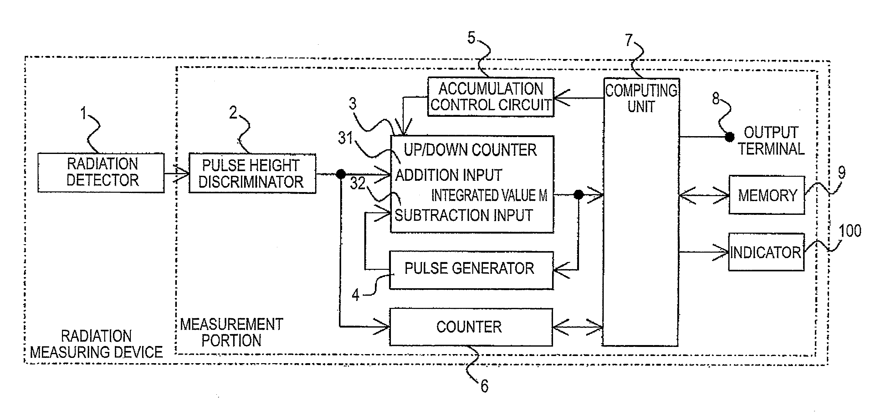
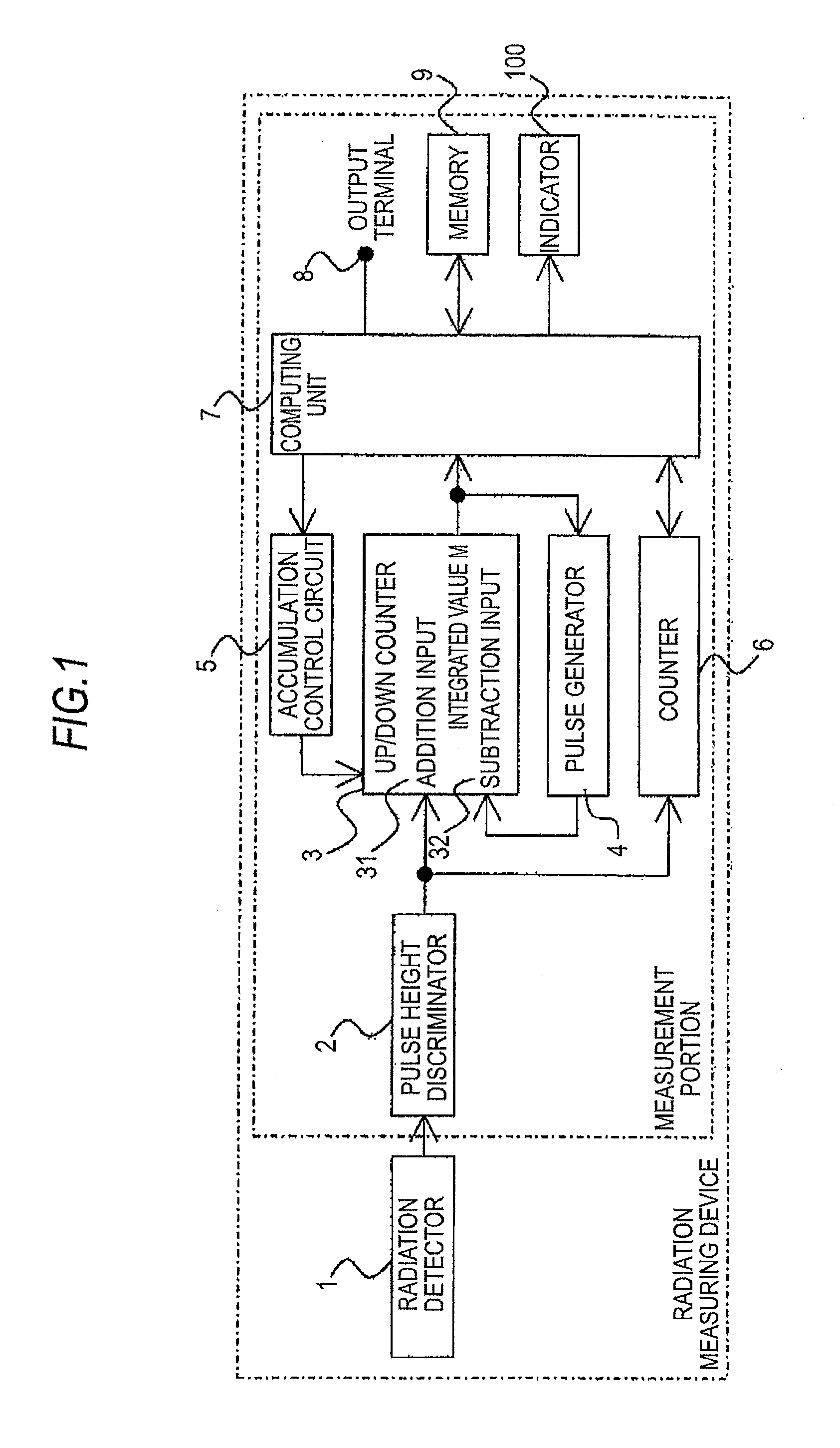
[0023]Hereinafter, a first embodiment of the invention will be described on the basis of the drawings. Referring to FIG. 1, a radiation detector 1 outputs an analog signal pulse upon detection of radiation and a pulse height discriminator 2 receives an input of the analog signal pulse outputted from the radiation detector 1 and outputs a digital pulse in a case where a voltage level of the analog signal pulse is as high as or higher than a predetermined level or within an allowable range. An up / down counter 3 receives an input of a digital pulse outputted from the pulse height discriminator 2 at an addition input 31 and an input of a digital pulse outputted from a pulse generator 4 at a subtraction input 32 in a fixed cycle. and thereby outputs the result as an integrated value. M.

[0024]An accumulation control circuit 5 controls the up / down counter 3 to count the pulses inputted to the addition input 31 and the subtraction input 32 of the up / down counter 3 by adding a weight on the ...

second embodiment

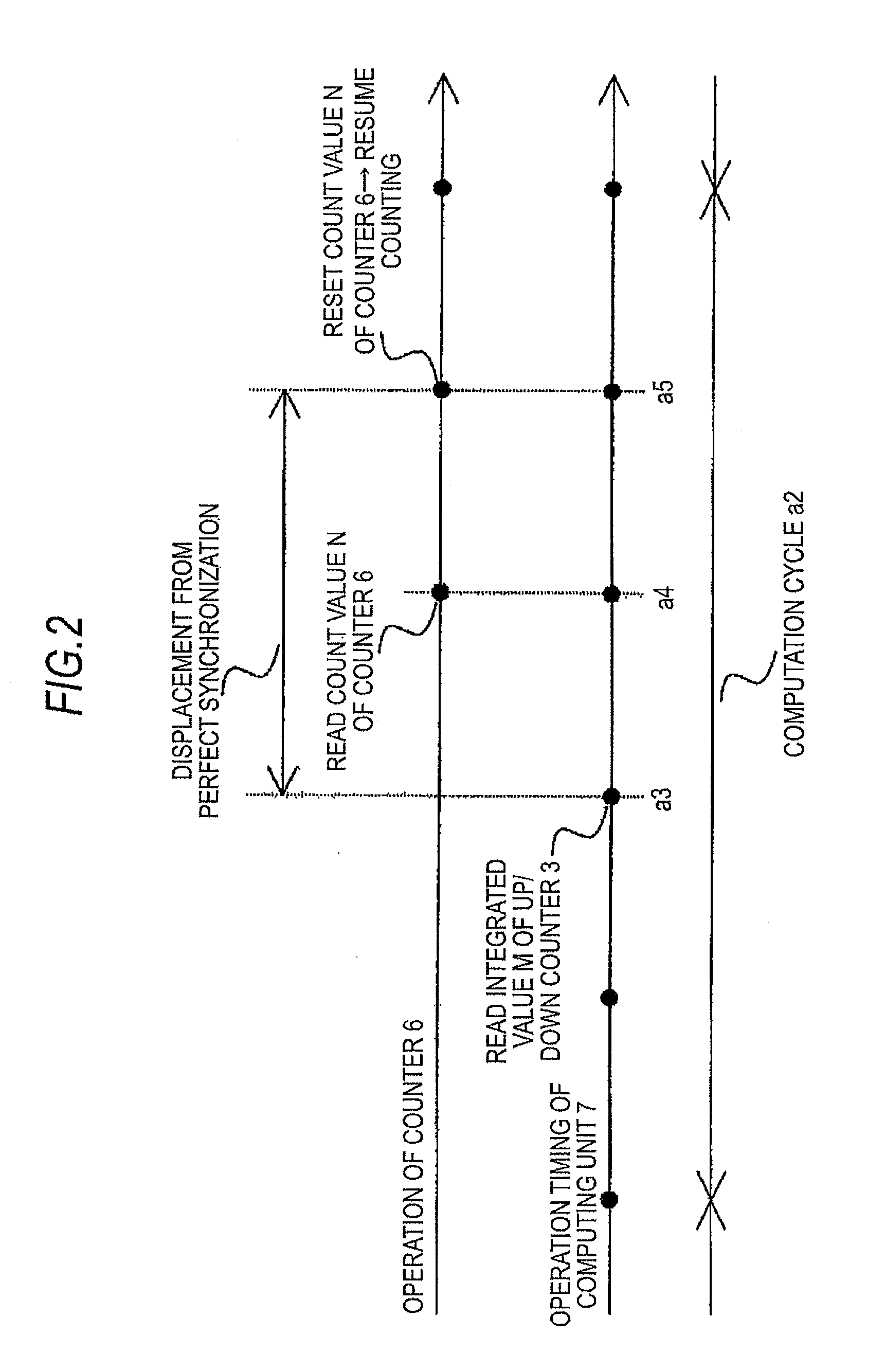
[0035]In the first embodiment above, the count value of the counter 6 is read in a fixed cycle by the computing unit 7 and the counter 6 is then reset to resume the counting. By contrast, in a second embodiment, as is shown in the time chart of FIG. 5, the reading is controlled sequentially by a pulse c1 of an internal clock (not shown) of the computing unit 7, and, for example, the count value N is read at timing c4 following timing c3 that is the read timing of the integrated value M in a computation cycle c2 of interest.

[0036]In the flowchart of FIG. 6, when N is near an overflow limit value NLIMIT, for example, smaller than ½NLIMIT (S11), the computing unit 7 returns to S1 without resetting the counter 6. When the count 6 has counted ½NLIMIT or more (S12), the computing unit 7 resets the counter 6 at timing c5 following timing c4 in a computation cycle c6 in which the counter 6 has counted ½NLIMIT or more to resume the counting from the start and returns to Step S1. There are tw...

third embodiment

[0037]In the first and second embodiments above, the radiation measurement value is indicated by the indicator 100 without a flicker. By contrast, in a third embodiment described with reference to the flowchart of FIG. 7, in a case where a net count value of the pulses inputted into the counter 6 in a computation cycle of interest is equivalent to or above the upper limit of the radiation measurement range (S21), the computing unit 7 sets a flag of a flicker to the radiation measurement value to be outputted to the indicator 100 from the computing unit 7 and returns to S1 (S22). In a case where the net count value is below the upper limit of the radiation measurement range (S23), the computing unit 7 sets no flag of a flicker to the radiation measurement value to be outputted to the indicator 100 from the computing unit 7 and returns to S1 (S24). Hence, the radiation measurement indicated by the indicator 100 can be visualized so that an individual can understand by a glance whether...


PUM


Abstract

A radiation measuring device includes a computing unit that receives an input of a count value of a count portion configured to receive an input of a digital pulse from a pulse height discriminator and count the digital pulse in a fixed cycle and an integrated value of an adder-subtractor accumulation portion configured to add the digital pulse and subtract a feedback pulse and finds a first current rate on the basis of the count value and the integrated value and a second count rate on the basis of the integrated value, so that soundness of the adder-subtractor accumulation portion is diagnosed and outputted by comparing the first count rate with the second count rate. A radiation measuring device of a simple configuration and a diagnosis method thereof enabling a high-accurate self-diagnosis online on the count rate measurement that is the keystone of the radiation measurement can be thus obtained.

Description

BACKGROUND OF THE INVENTION[0001]1. Field of the Invention[0002]The present invention relates to a radiation measuring device forming a radiation monitor used for emission management or radiation management in a nuclear reactor installation and a spent fuel reprocessing facility and to a diagnostic method thereof.[0003]2. Background Art[0004]A requirement for a radiation measuring device used in a nuclear reactor installation, a spent fuel reprocessing facility, and so forth is an ability to enable measurement covering a broad range of the input repetition frequency of a signal pulse as the detection result of radiation in the order of 10 cpm to 107 cpm. In order to eliminate discontinuity accompanying range switching, count rate measurement using an up / down counter operating at a high speed in a broad range without switching ranges is carried out. According to this measuring method, a count rate is computed by reading an integrated value when an addition input of the up / down counte...

Claims


Application Information

Patent Timeline
Patent Type & Authority Applications(United States)
IPC IPC(8): G01T1/00G01T7/00G06F15/00
CPCG01T1/17
Inventor HAYASHI, MASATERUMOTEKI, KENICHINAKANISHI, MASAKAZU
Owner MITSUBISHI ELECTRIC CORP
Why Eureka
Try Eureka