Self-Aspirated Reciprocating Internal Combustion Engine

a reciprocating internal combustion engine and self-aspiration technology, which is applied in the direction of positive displacement engines, machines/engines, mechanical equipment, etc., can solve the problems of piston slap against the cylinder wall, and achieve the effects of reducing vibration, reducing shaft counter weight, and improving efficiency

Inactive Publication Date: 2011-06-23
FISHER PATRICK T
View PDF5 Cites 37 Cited by
  • Summary
  • Abstract
  • Description
  • Claims
  • Application Information

AI Technical Summary

Benefits of technology

[0027]Another alternative of the invention is a one or three-lobe cam with three or six cylinders radially spaced about a power shaft that operate with three sets of follower arms, links and cam followers. When using a three-lobe cam, this arrangement provides offsetting inertia forces for the reciprocating components, thereby eliminating shaft counter weights.
[0028]A simple structure beam machine of the invention consists of a single throw crankshaft beam mechanism similar to the invention's cam beam mechanism except the cam, links and cam followers are replaced with a crankshaft and beam rod(s). Compared to the cam beam, the crankshaft beam arrangement has more vibration because of rod angularity. The centrally located piston(s) provide the same piston dwell as prior art, but the invention's outer pistons provide up ...

Problems solved by technology

Piston knocking is a problem for conventional diesel engines which have high combus...

Method used


Image

  • Self-Aspirated Reciprocating Internal Combustion Engine
  • Self-Aspirated Reciprocating Internal Combustion Engine
  • Self-Aspirated Reciprocating Internal Combustion Engine

Examples


Embodiment Construction

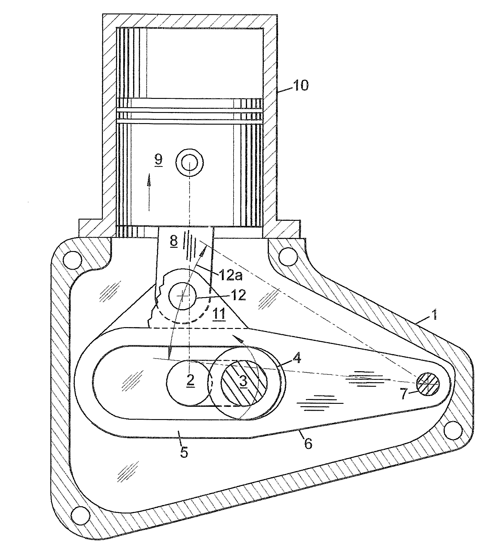
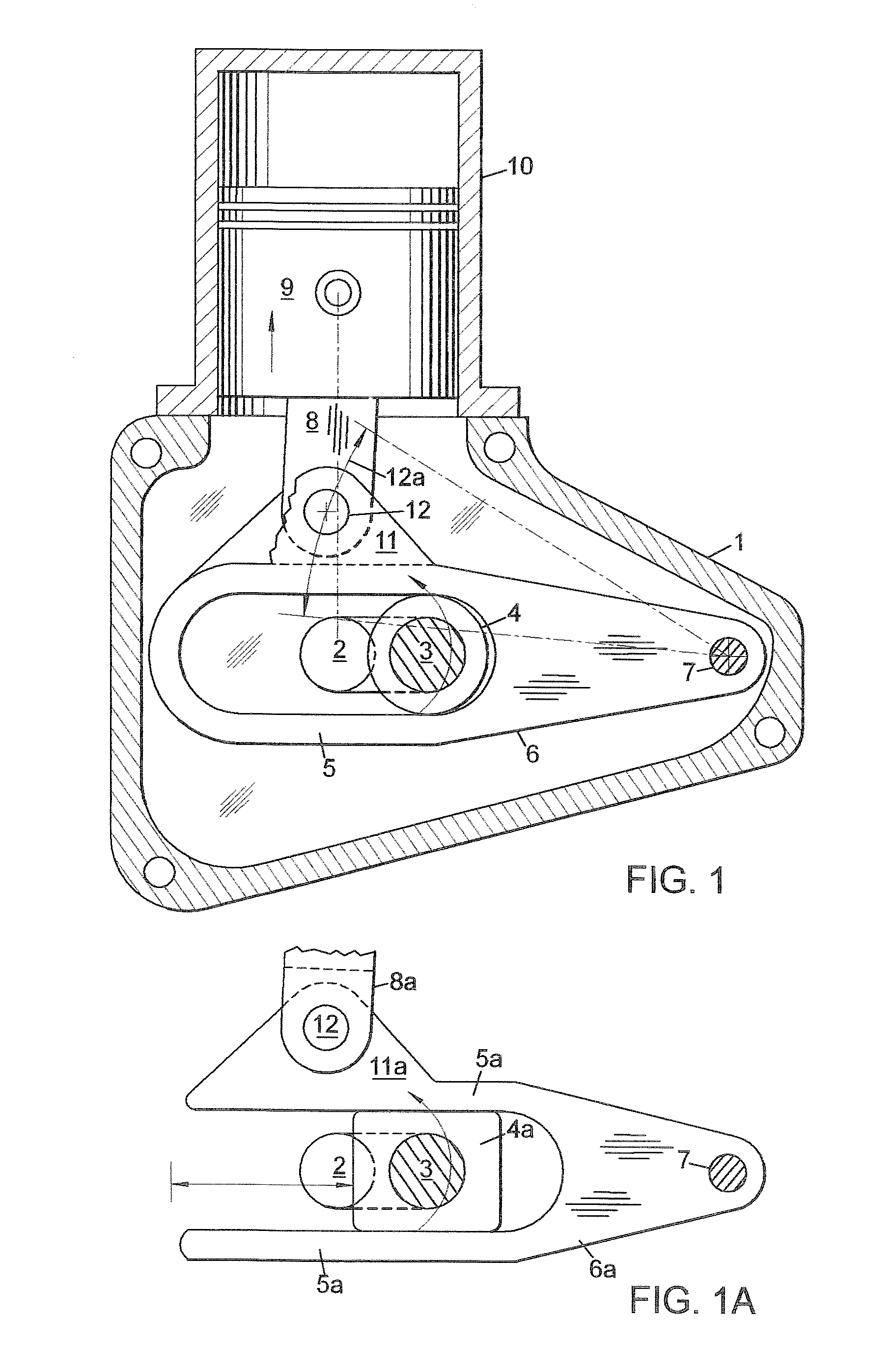
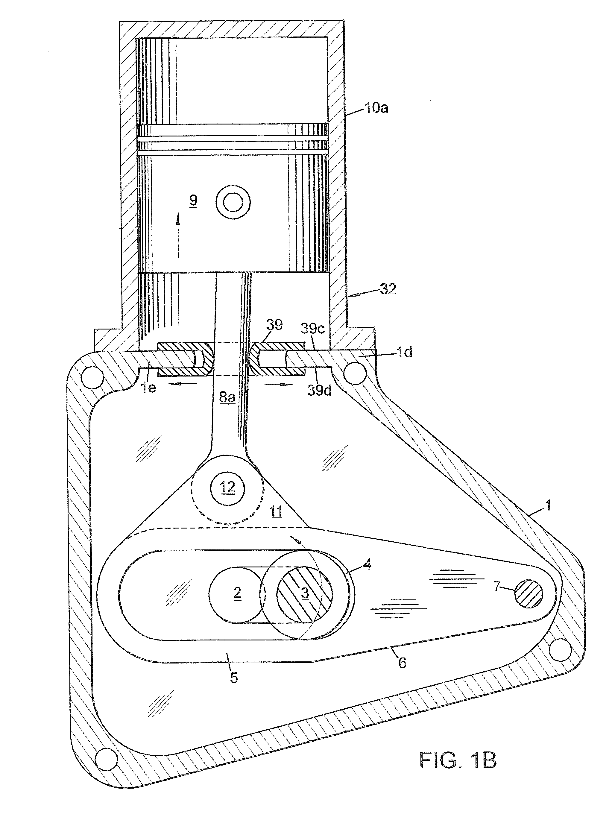
[0062]The invention provides reciprocating piston machines with novel yoke-arm crankshaft, plate cam and eccentric beam mechanisms which include the new and improved use of pivoting arms. Reduced piston friction and increased piston dwell are some of the fundamental advantages featured by the invention. Some arrangements described are: (1) single-cylinder, (2) in-line twin, (3) opposed two-cylinder, (4) V-twin, and (5) semiradial and radial.

[0063]These reciprocating piston machines relate to internal combustion engines, compressors, steam engines, fluid motors and pumps; the machines operate with piston power drive equipment that includes vehicles, aircraft, boats, air conditioners and power tools.

[0064]FIGS. 1-5 are arranged and function somewhat similar to conventional crankshaft engines except for the addition of yoke-arm(s) 6 and crankpin roller bearing(s) 4 that provide significant advantages.

[0065]In FIG. 1, there is shown one embodiment of the invention that is a single-cylin...


PUM


Abstract

Disclosed are crankshaft, single-plate cam and beam mechanisms that provide significant improvements in performance for 2- & 4-stroke engines, compressors and pumps. These cost effective mechanisms include linkages with the new and improved use of pivoting arms that operate with a variety of cylinder arrangements. One embodiment of the crankshaft mechanism has its crankpin roller positioned within a novel yoke-arm. The cam mechanism uses a pair of centrally positioned parallel links that are connected to roller cam followers and single or diametrically-opposed pistons. A pair of laterally extending follower arms connects to the ends of the links to provide support and alignment for the piston rods. Between the reciprocating links, cam followers and follower arms is a rotating odd-lobe plate cam. A beam mechanism uses opposite-direction extending balancing beams that are connected to links, cam followers and piston rods.

Description

CROSS-REFERENCE TO RELATED APPLICATIONS[0001]This application is a divisional of U.S. Ser. No. 11 / 226,794, filed Sep. 14, 2005, now U.S. Pat. No. 7,328,682 B2, issued Feb. 12, 2008, entitled “Improved Efficiencies for Piston Engines or Machines”, and U.S. Ser. No. 11 / 958,198, filed Dec. 17, 2007, now U.S. Pat. No. 7,552,707 B2, issued Jun. 30, 2009, entitled “Efficiencies for Cam-Drive Piston Engines or Machines,”, and U.S. Ser. No. 12 / 425,879, filed Apr. 17, 2009, entitled “Crankshaft Beam Piston Engine or Machine” the disclosures of which are incorporated herein by reference in their entirety for all purposes.STATEMENT REGARDING FEDERALLY SPONSORED RESEARCH OR DEVELOPMENT[0002]Not applicableREFERENCE TO MICROFICHE APPENDIX[0003]Not applicableTECHNICAL FIELD OF THE INVENTION[0004]The present invention relates to reciprocating piston power drive equipment that operates with reciprocating engines, compressors, fluid motors and pumps. Piston equipment includes vehicles, aircraft, boat...

Claims


Application Information

Patent Timeline
IPC IPC(8): F02B33/06F02B75/32F02F11/00
CPCF01B9/047F01B9/06F01B2009/063F01B2009/066F02B33/06F02B33/20F16J7/00F02B75/16F02B75/22F02B75/222F02B75/282F02B75/32F02B33/22
Inventor FISHER, PATRICK T.
Owner FISHER PATRICK T
Why Eureka
Try Eureka