
Apparatus and Method for Controlling Semiconductor Die Warpage

Active Publication Date: 2011-06-23
QUALCOMM INC
View PDF13 Cites 29 Cited by
  • Summary
  • Abstract
  • Description
  • Claims
  • Application Information

AI Technical Summary

Benefits of technology

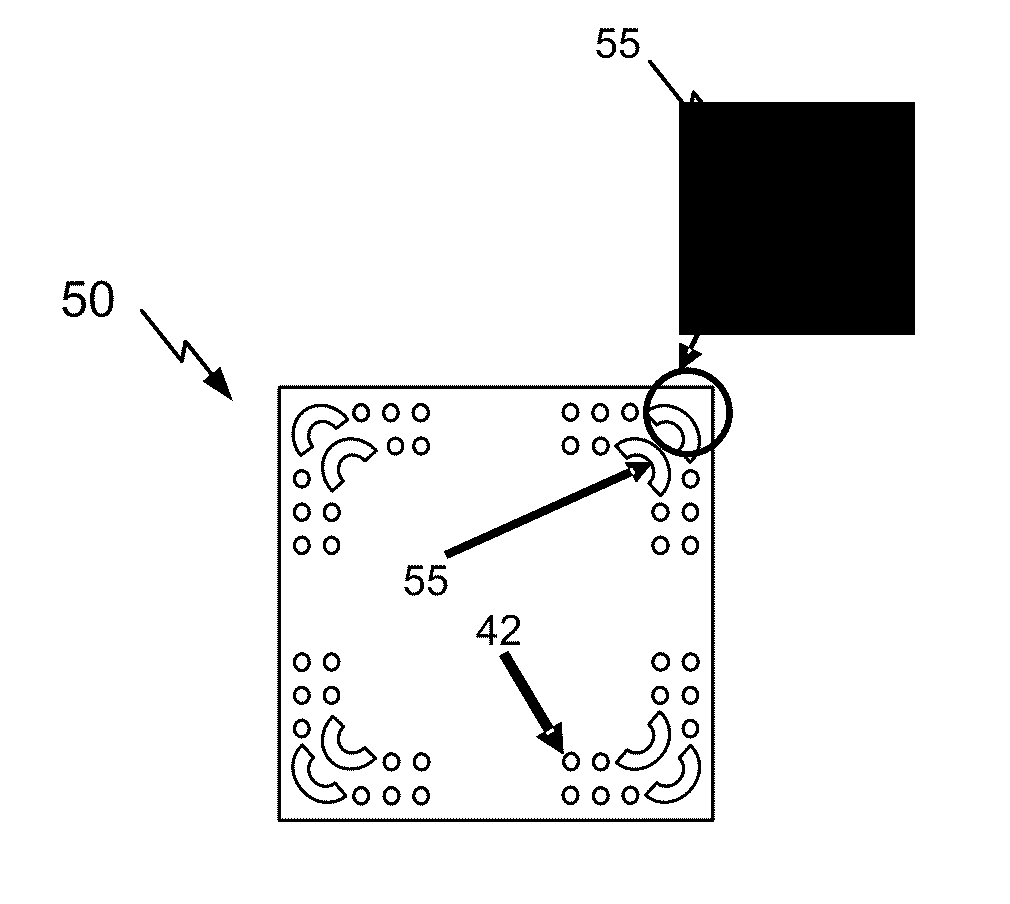
[0009]According to an aspect of the present disclosure, a semiconductor die has through silicon vias located in a peripheral region. The through silicon vias reduce warpage of the semiconductor die.
[0010]In another aspect, a method for manufacturing a semiconductor die includes fabricating a plurality of non-signal carrying through silicon vias in a peripheral region of the semiconductor die to reduce warpage of the die.
[0011]In yet another aspect, a semiconductor die has means for increasing a coefficient of thermal expansion (CTE) of the semiconductor die located in a peripheral region of the semiconductor die. The CTE increasing means reduces warpage of the semiconductor die.
[0012]In still another aspect, a computerized method for designing a semiconductor die includes determining locations for stress relief through silicon vias in order to reduce die warpage.

Problems solved by technology

Residual stress in semiconductor wafers and dies causes warpage.
For example, deposited materials (e.g., to create transistors) on the wafer can be engineered to have a different stress than the substrate resulting in unbalanced stress.
When the stress between the substrate and deposited materials is unbalanced, the substrate may warp or bend to reach an equilibrium stress.
In addition, change of temperature experienced by a packaged die can cause warpage.
Warpage occurs as a result of the CTE mismatch between the material sets of the package and die.
The warpage is exacerbated when there is a substantial thickness difference between the package and the die.
As a result of the substantial thickness difference, severe warpage may occur.
When the warping is severe, inadequate bonding of the die to the package occurs.
If the warpage occurs after assembly, the bumps or pillars may de-attach when an end user device is with the consumer.
In addition, interconnect fatigue life decreases when the coefficient of thermal expansion (CTE) between the die and package substrate are mismatched.
The strain concentrated at the corner of chip results in a crack that propagates out from the corner.
As the crack propagates, it opens up either the chip-underfill interface or another weak interface, causing either interconnect fatigue or electrical failure in the chip dielectric.
Although stress engineering solutions involving die dielectric interfaces exist, such solutions are relatively complex and expensive.

Method used


Image

  • Apparatus and Method for Controlling Semiconductor Die Warpage
  • Apparatus and Method for Controlling Semiconductor Die Warpage
  • Apparatus and Method for Controlling Semiconductor Die Warpage

Examples


Embodiment Construction

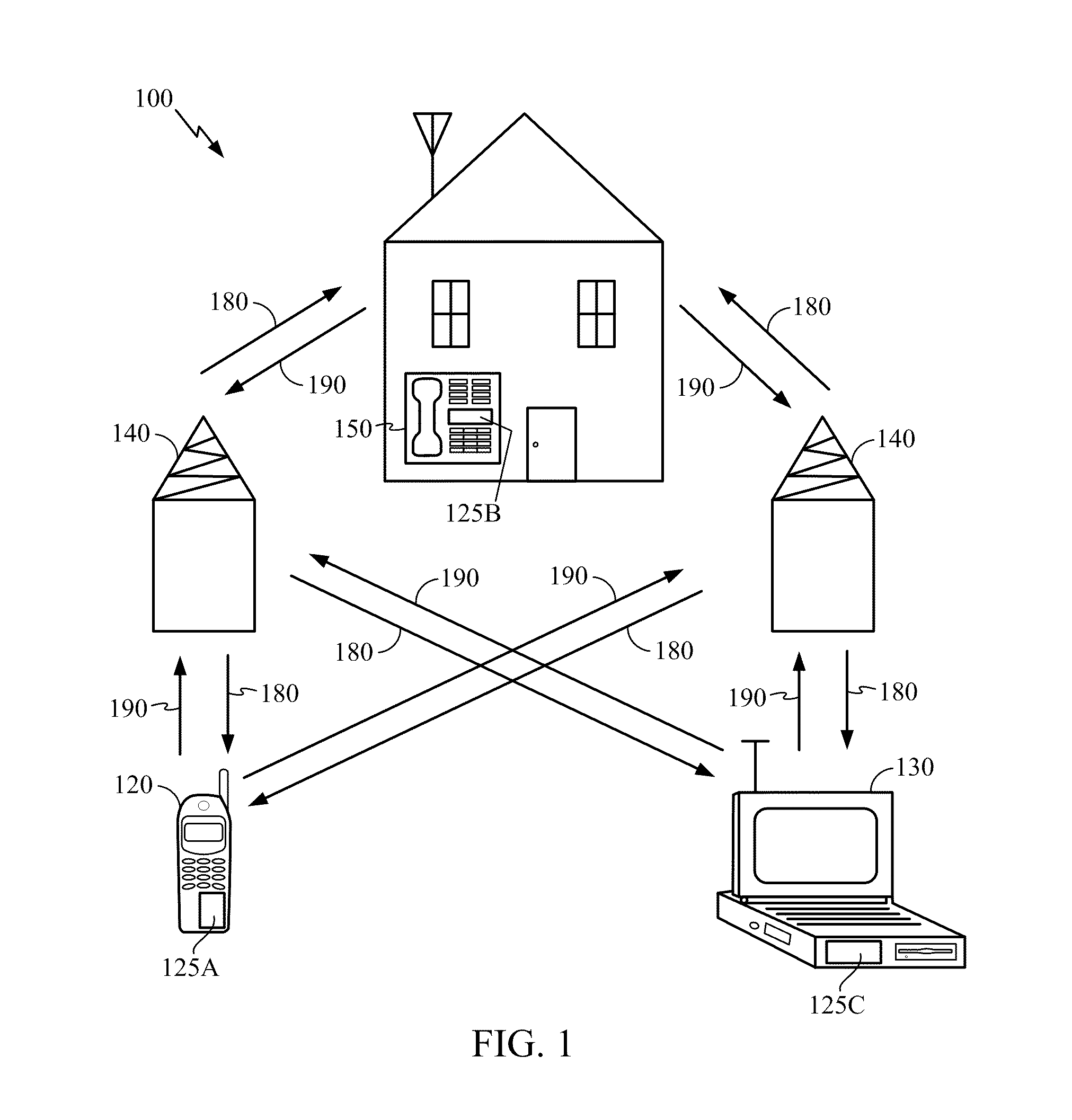
[0020]FIG. 1 is a block diagram showing an exemplary wireless communication system 100 in which an embodiment of the disclosure may be advantageously employed. For purposes of illustration, FIG. 1 shows three remote units 120, 130, and 150 and two base stations 140. It will be recognized that wireless communication systems may have many more remote units and base stations. Remote units 120, 130, and 150 include IC devices 125A, 125B and 125C, that include the disclosed semiconductor die. It will be recognized that any device containing an IC may also include the die disclosed here, including the base stations, switching devices, and network equipment. FIG. 1 shows forward link signals 180 from the base station 140 to the remote units 120, 130, and 150 and reverse link signals 190 from the remote units 120, 130, and150 to base stations 140.

[0021]In FIG. 1, the remote unit 120 is shown as a mobile telephone, the remote unit 130 is shown as a portable computer, and the remote unit 150 ...


PUM


Abstract

A semiconductor die has through silicon vias arranged to reduce warpage. The through silicon vias adjust the coefficient of thermal expansion of the semiconductor die, permit substrate deformation, and also relieve residual stress. The through silicon vias may be located in the edges and / or corners of the semiconductor die. The through silicon vias are stress relief vias that can be supplemented with round corner vias to reducing warpage of the semiconductor die.

Description

TECHNICAL FIELD[0001]The present disclosure generally relates to semiconductor die manufacturing. More specifically, the present disclosure relates to controlling warpage while manufacturing semiconductor dies.BACKGROUND[0002]Residual stress in semiconductor wafers and dies causes warpage. For example, deposited materials (e.g., to create transistors) on the wafer can be engineered to have a different stress than the substrate resulting in unbalanced stress. In other cases, the stresses are not engineered but merely result from different materials. When the stress between the substrate and deposited materials is unbalanced, the substrate may warp or bend to reach an equilibrium stress.[0003]In addition, change of temperature experienced by a packaged die can cause warpage. The coefficient of thermal expansion (CTE) of the package differs from the CTE of the die. Warpage occurs as a result of the CTE mismatch between the material sets of the package and die. The warpage is exacerbate...

Claims


Application Information

Patent Timeline
IPC IPC(8): H01L23/00H01L21/768G06F17/50
CPCH01L23/3128H01L23/3677H01L2924/15311H01L23/562H01L2224/16225H01L23/481H01L21/28H01L23/48
Inventor BAI, XUERAY, URMI
Owner QUALCOMM INC
Learn More