LED lighting tube adopting isolated fluorescent conversion technology

Inactive Publication Date: 2011-06-23
SHENZHEN CGX LED LIGHTING INDAL
View PDF9 Cites 6 Cited by
  • Summary
  • Abstract
  • Description
  • Claims
  • Application Information

AI Technical Summary

Benefits of technology

[0016]The phosphor layer of the white light conversion film is isolated from the LED chip array, which avoids the temperature of the phosphor heating up and the aging of the phosphor, thereby improves the service life of the LED lighting tube. The phosphor is uniformly disposed in the phosphor layer, thereby improving the brightness uniformity of the LED lighting tube. Furthermore, compared to traditional art, the LED lighting t

Problems solved by technology

Furthermore, fluorescent tubes contain heavy metals like mercury and etc, and can not be recycled after the disuse under the conditions of the existing technology.
Heavy metal materials generated by the cracked tube may harm the environment and human.
The main drawbacks of this technology are:
It is difficult to control the phosphor uniformity when coating a blue LED chip with phosphor powder, which leads to the poor brightness uniformity of the finished white LED products.
It is also difficult to adjust the color temperature of white LED lamps after the finished products are formed.
The phosphor directly contact

Method used


Image

  • LED lighting tube adopting isolated fluorescent conversion technology
  • LED lighting tube adopting isolated fluorescent conversion technology
  • LED lighting tube adopting isolated fluorescent conversion technology

Examples


embodiment 1

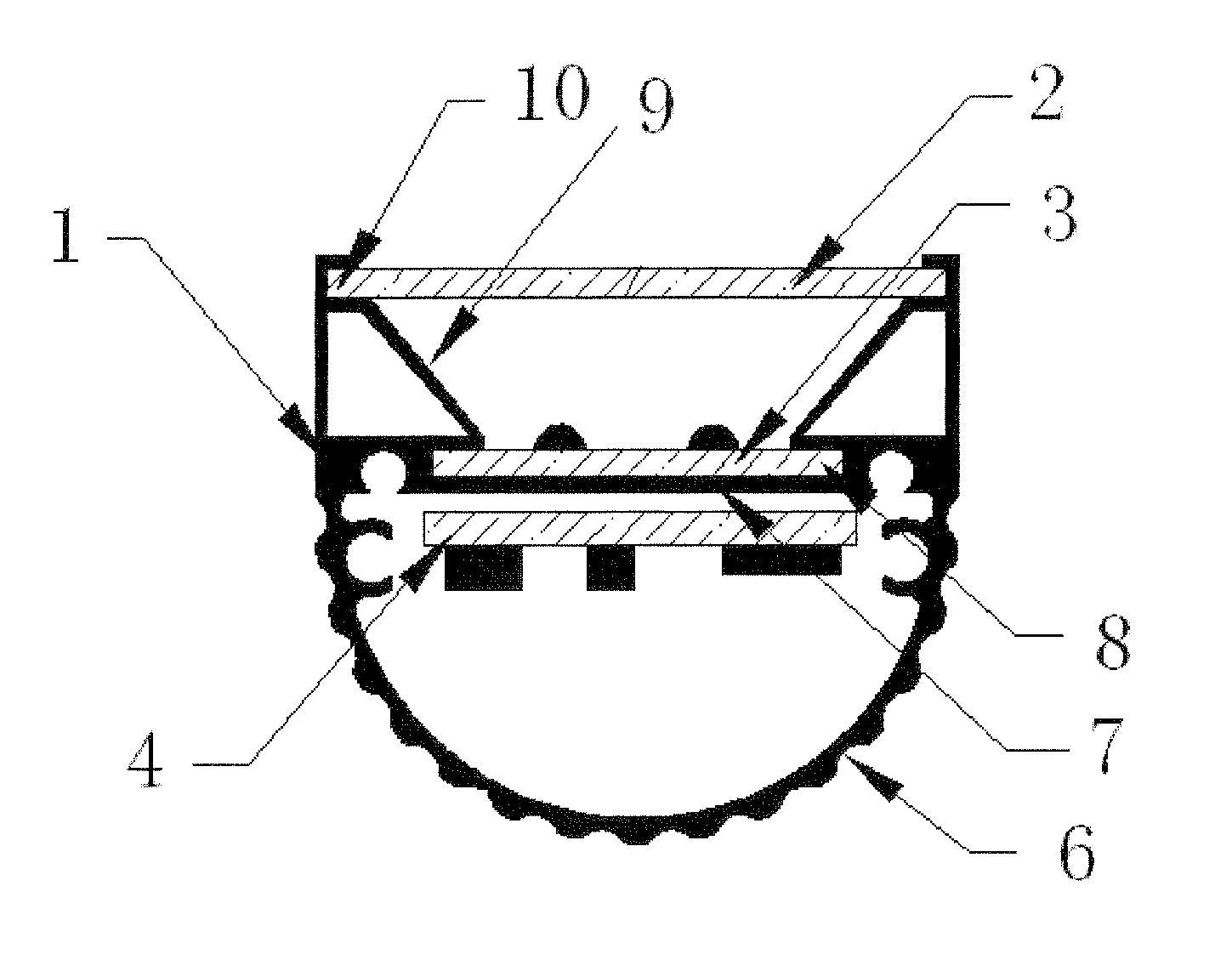
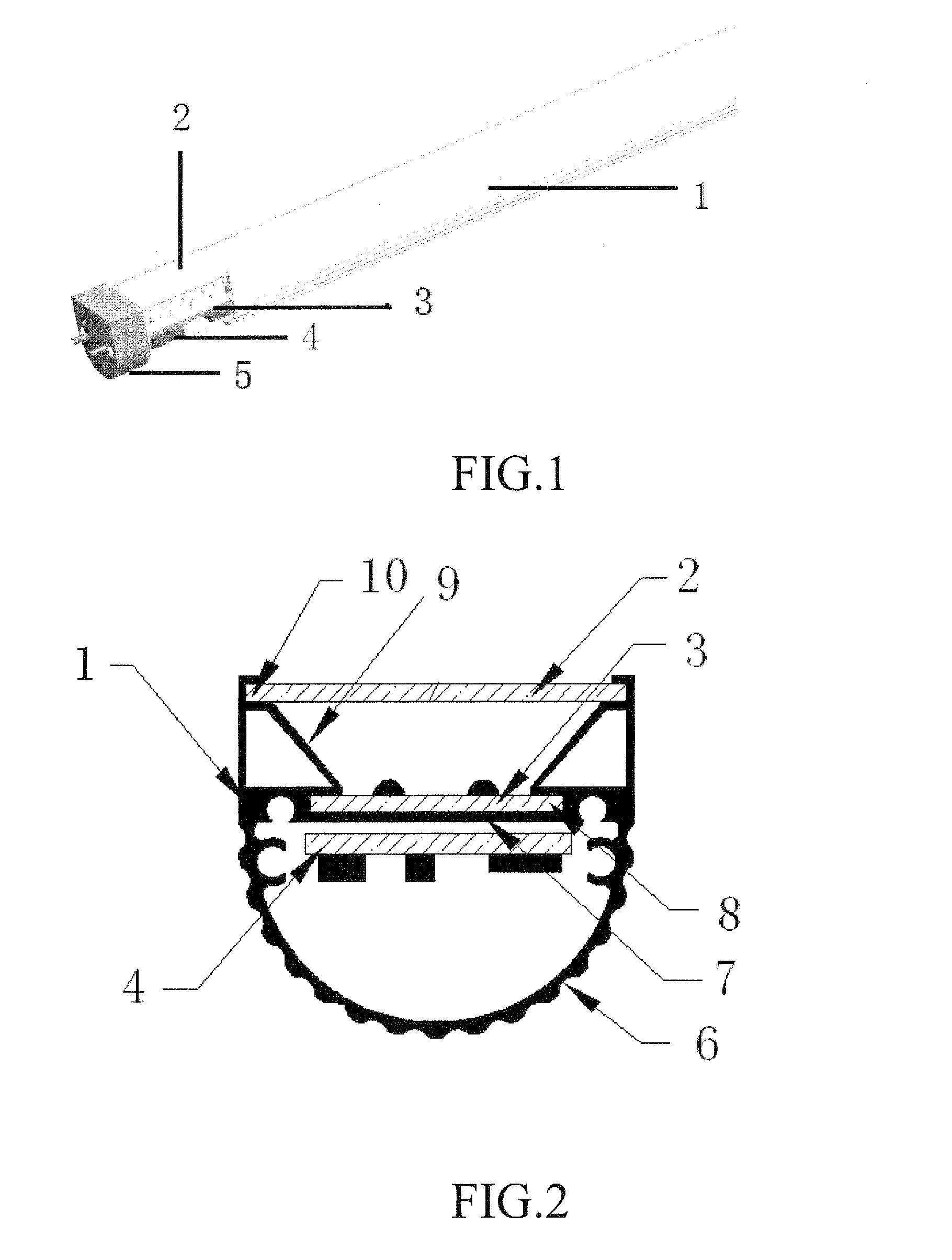
[0023]Referring to FIGS. 1 and 2, an LED lighting tube in accordance with a first embodiment of the invention includes a metal shell 1, a white light conversion film 2, a LED light source 3 for emitting blue or purple or UV (ultraviolet) light, a driving power supply 4, and holders 5. The metal shell 1 has a strip-shaped form. The metal shell 1 includes a thin board 7 whose edge contacting with an inner wall of the metal shell 1. The thin board 7 defines two slots 8 in both sides thereof; for fixing the LED light source 3. Each of two slopes 9 has a lower edge contacting with the thin board and an upper edge. The slopes 9 have a reflective layer on a surface thereof; for improving the luminous efficiency of LED lighting tube. Each of two receiving board (not label) has an edge contacting with the inner wall of the metal shell 1 and an opposite edge contacting with the upper edge of a corresponding slope 9. Each receiving board defines a slot 10. The two slots 10 corporately receive ...

embodiment 2

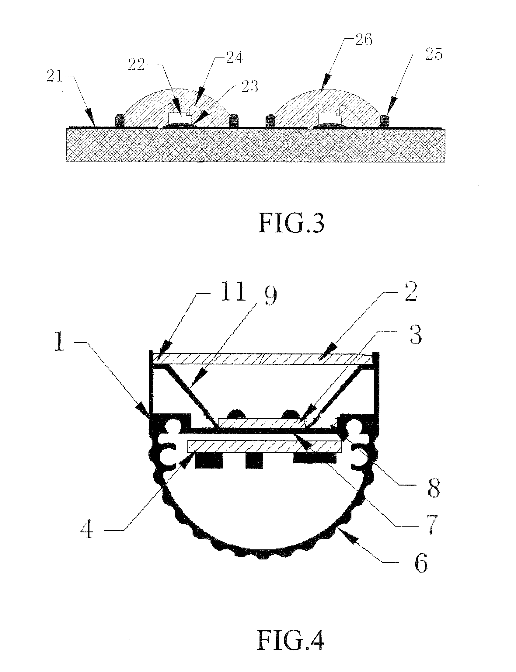
[0027]Referring to FIG. 4, an LED lighting tube in accordance with a second embodiment of the invention includes a metal shell 1, a white light conversion film 2, a LED light source 3 for emitting blue or purple or UV light, a driving power supply 4, and holders 5. The metal shell 1 has a strip-shaped form. The metal shell 1 includes a thin board 7 whose edge contacting with an inner wall of the metal shell 1. Each of two slopes 9 has a lower edge contacting with the thin board and an upper edge. The slopes 9 have a reflective layer on a surface thereof, for improving the luminous efficiency of LED lighting tube. Each of two receiving board 11 has an edge contacting with the inner wall of the metal shell 1 and an opposite edge contacting with the upper edge of a corresponding slope 9. A surface of the metal shell 1 is configured with more than one convex edge for increasing the area of heat elimination.

[0028]The white light conversion film 2 is fixed to the thin board 7 via adhesive...


PUM


Abstract

An LED lighting tube includes a strip-shaped metal shell, a LED light source, a white light conversion film, and a driving power supply. The metal shell defines two spaced slots inwardly. The white light conversion film and the LED light source are respectively fixed in the two slots. The white light conversion film is isolated from the LED light source. The driving power supply is accommodated in the metal shell.

Description

BACKGROUND OF THE INVENTION[0001]a) Field of the Invention[0002]This invention relates to one light source, and specifically relates to a kind of LED lighting tube.[0003]b) Description of the Prior Art[0004]In recent years, the rapid development of white LED is gradually entering the field of common lighting. Compared with fluorescent lamp, LED lighting source has the features of long service life, high luminous efficiency, and low energy consumption. Furthermore, fluorescent tubes contain heavy metals like mercury and etc, and can not be recycled after the disuse under the conditions of the existing technology. Heavy metal materials generated by the cracked tube may harm the environment and human. Compared with the fluorescent lamp, LED lighting source can solve the problems of high energy consumption, short service life, and impact of heavy metals on the environment and human after the disuse.[0005]Prior white LED lighting tube is manufactured by assembling packaged white LED devi...

Claims


Application Information

Patent Timeline
IPC IPC(8): H01J13/46H01K1/62F21V9/40
CPCF21K9/00F21Y2103/003F21K9/17F21Y2101/02F21K9/64F21K9/27F21Y2103/10F21Y2115/10
Inventor LI, BINGQIANPENG, HONGCUNWANG, WEIGUO
Owner SHENZHEN CGX LED LIGHTING INDAL
Why Eureka
Try Eureka