Digital RF converter, digital RF modulator and transmitter including the same

a digital rf converter and digital rf modulator technology, applied in the field of digital rf converters, can solve the problems of increasing the number of cells, affecting the entire performance of the transmitter system, and affecting the signal to be transmitted bandwidth, so as to improve the signal to noise ratio of the transmitter and improve the entire dynamic rang

Active Publication Date: 2011-06-23
ELECTRONICS & TELECOMM RES INST
View PDF13 Cites 15 Cited by
  • Summary
  • Abstract
  • Description
  • Claims
  • Application Information

AI Technical Summary

Benefits of technology

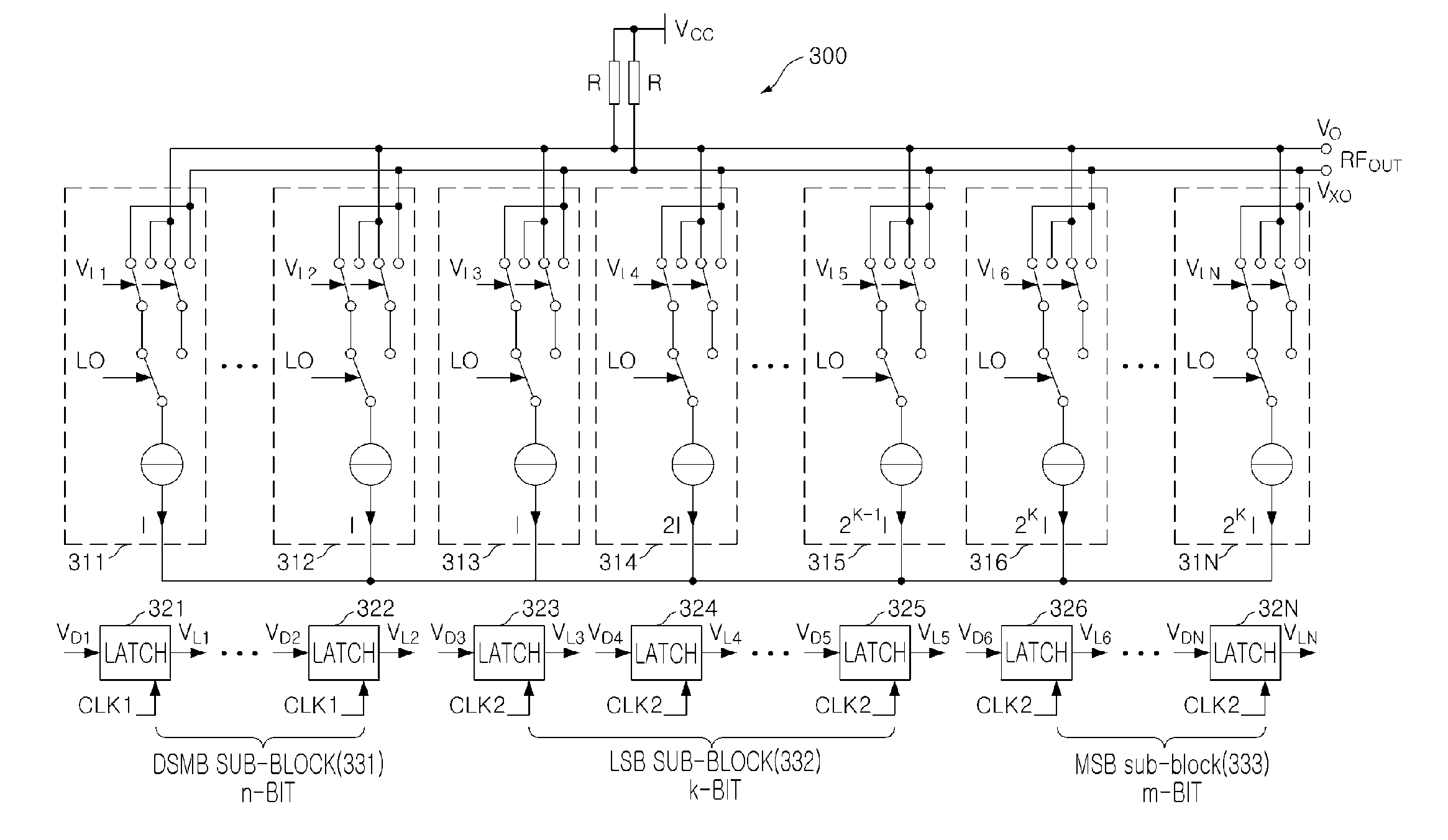
[0017]An aspect of the present invention provides a digital RF converter using the existing digital RF converting cells, controlling baseband signals of each cell with digital signals, and applying sigma-delta modulated signals to a plurality of additional cells in order to generate current having a smaller magnitude than current generated by one cell having the smallest size, thereby making it possible to improve the entire dynamic range and a signal to noise ratio of a transmitter, and a digital RF modulator and a transmitter including the same.

Problems solved by technology

First, the entire performance of the transmitter system may be deteriorated due to non-ideal operations of analog circuits such as non-linearity, carrier feedthrough, and so on, of the mixer and the low pass filter included in the transmitter circuit.
Second, a bandwidth of a signal to be transmitted is limited due to analog baseband circuits.
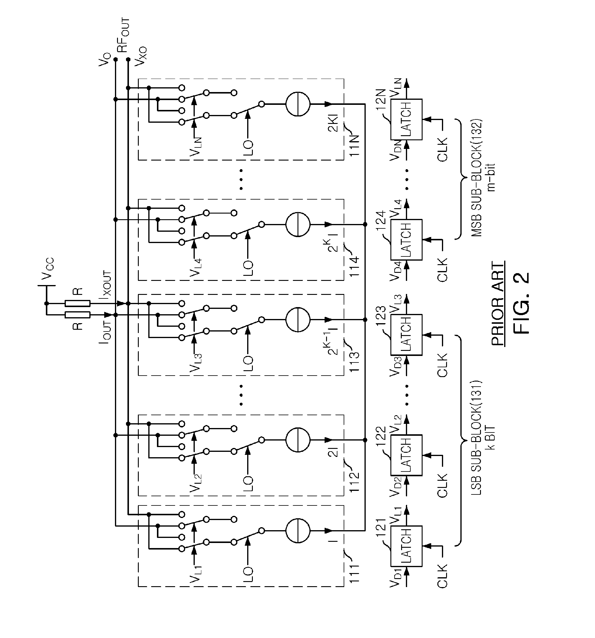
Further, if each cell is designed to have the same unit-weight, the entire linearity of the transmission system is getting better, but the number of cells is increased such that the semiconductor circuit layout design becomes complicated and the electrical coupling in the circuit becomes large to increase the signal interference and the design area.

Method used


Image

  • Digital RF converter, digital RF modulator and transmitter including the same
  • Digital RF converter, digital RF modulator and transmitter including the same
  • Digital RF converter, digital RF modulator and transmitter including the same

Examples


Embodiment Construction

[0041]Although the present invention can be modified variously and have several embodiments, the exemplary embodiments are illustrated in the accompanying drawings and will be described in detail in the detailed description.

[0042]However, the present invention is not limited to the specific embodiments and should be construed as including all the changes, equivalents, and substitutions included in the spirit and scope of the present invention.

[0043]Further, terms used in the specification, ‘first’, ‘second’, etc. can be used to describe various components, but the components are not to be construed as being limited to the terms. The terms are only used to differentiate one component from other components. For example, the first component may be called the second component without departing from the scope of the present invention. Likewise, the second component may be called the first component. The term ‘and / or’ includes a combination of a plurality of items or any one of a pluralit...


PUM


Abstract

There are provided a digital RF converter capable of improving a dynamic range and a signal to noise ratio of a transmitter and a digital RF modulator and a transmitter including the same. The digital RF converter may include: a delta-sigma modulated bits (DSMB) sub-block that generates a current magnitude corresponding to least-significant n bits among input signals at a first sampling speed; a least-significant bit (LSB) sub-block that generates a current magnitude corresponding to intermediate k bits among the input signals at a second sampling speed lower than the first sampling speed; and a most-significant bit (MSB) sub block that generates a current magnitude corresponding to most-significant m bits among the inputs signals at the second sampling speed.

Description

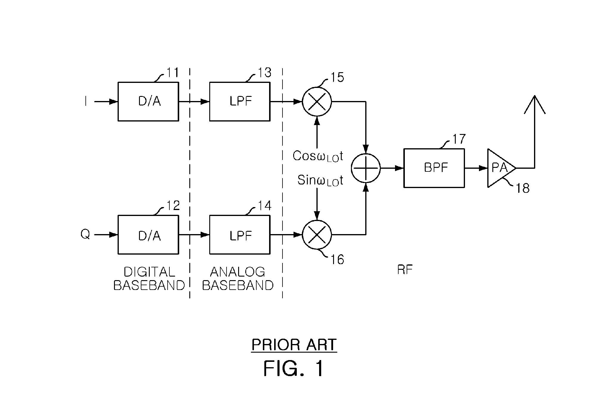
CROSS-REFERENCE TO RELATED APPLICATIONS[0001]This application claims the priorities of Korean Patent Application Nos. 10-2009-0127518 filed on Dec. 18, 2009 and 10-2010-0027986 filed on Mar. 29, 2010, in the Korean Intellectual Property Office, the disclosures of which are incorporated herein by reference.BACKGROUND OF THE INVENTION[0002]1. Field of the Invention[0003]The present invention relates to a digital RF converter, and more particularly, to a digital RF converter capable of improving a dynamic range of a transmitter and a signal to noise ratio, a digital RF modulator and a transmitter including the same.[0004]2. Description of the Related Art[0005]In wireless communication applications, the design thereof has been continuously developed to have simple and inexpensive wireless architectural structures which can increase integration in mobile terminals.[0006]FIG. 1 shows a general analog circuit based transmitter. Referring to FIG. 1, the transmitter circuit includes digital-...

Claims


Application Information

Patent Timeline
Patent Type & Authority Applications(United States)
IPC IPC(8): H04L27/00H03M3/02H03M1/66
CPCH03M1/68H03M1/687H03M3/50H03M1/747H03M1/745
Inventor YU, HYUN KYUCHOI, JANG HONGBOO, HYUN HOPARK, PIL JAEPARK, MUN YANGKIM, SEONG DOSHIM, SUN BOHONG, SONG CHEOL
Owner ELECTRONICS & TELECOMM RES INST
Why Eureka
Try Eureka