
Implantable heart assist system

a heart assist and implantable technology, applied in the field of implantable heart assist systems, can solve the problems of reducing cardiac output, heart failure, and reducing cardiac output, and achieve the effect of reducing electrical noise and reducing the stress on the wires

Inactive Publication Date: 2011-06-23
TC1 LLC
View PDF3 Cites 25 Cited by
  • Summary
  • Abstract
  • Description
  • Claims
  • Application Information

AI Technical Summary

Benefits of technology

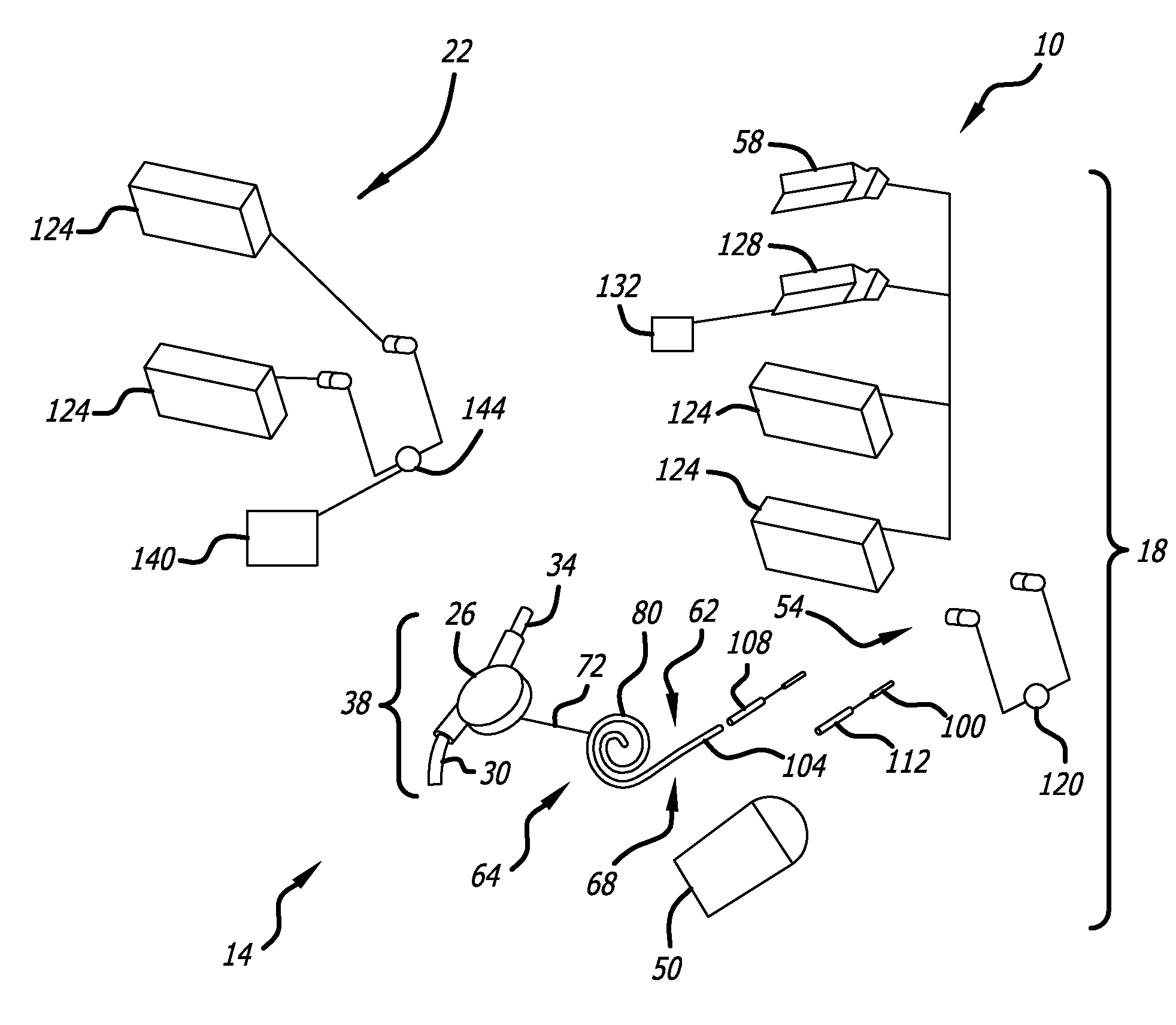
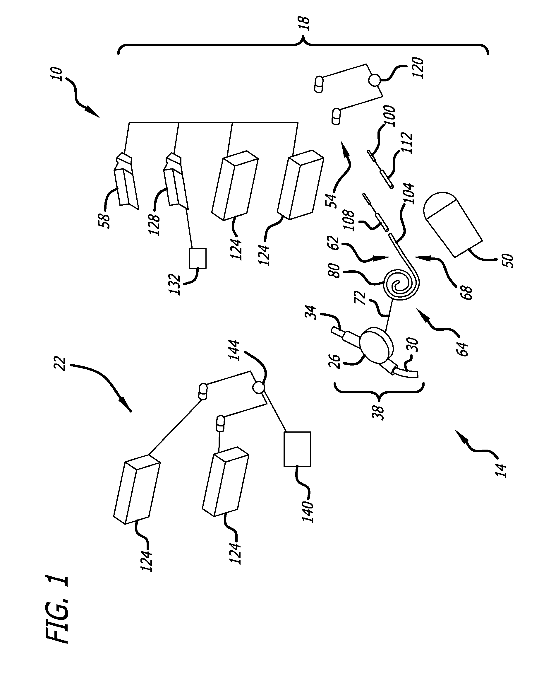
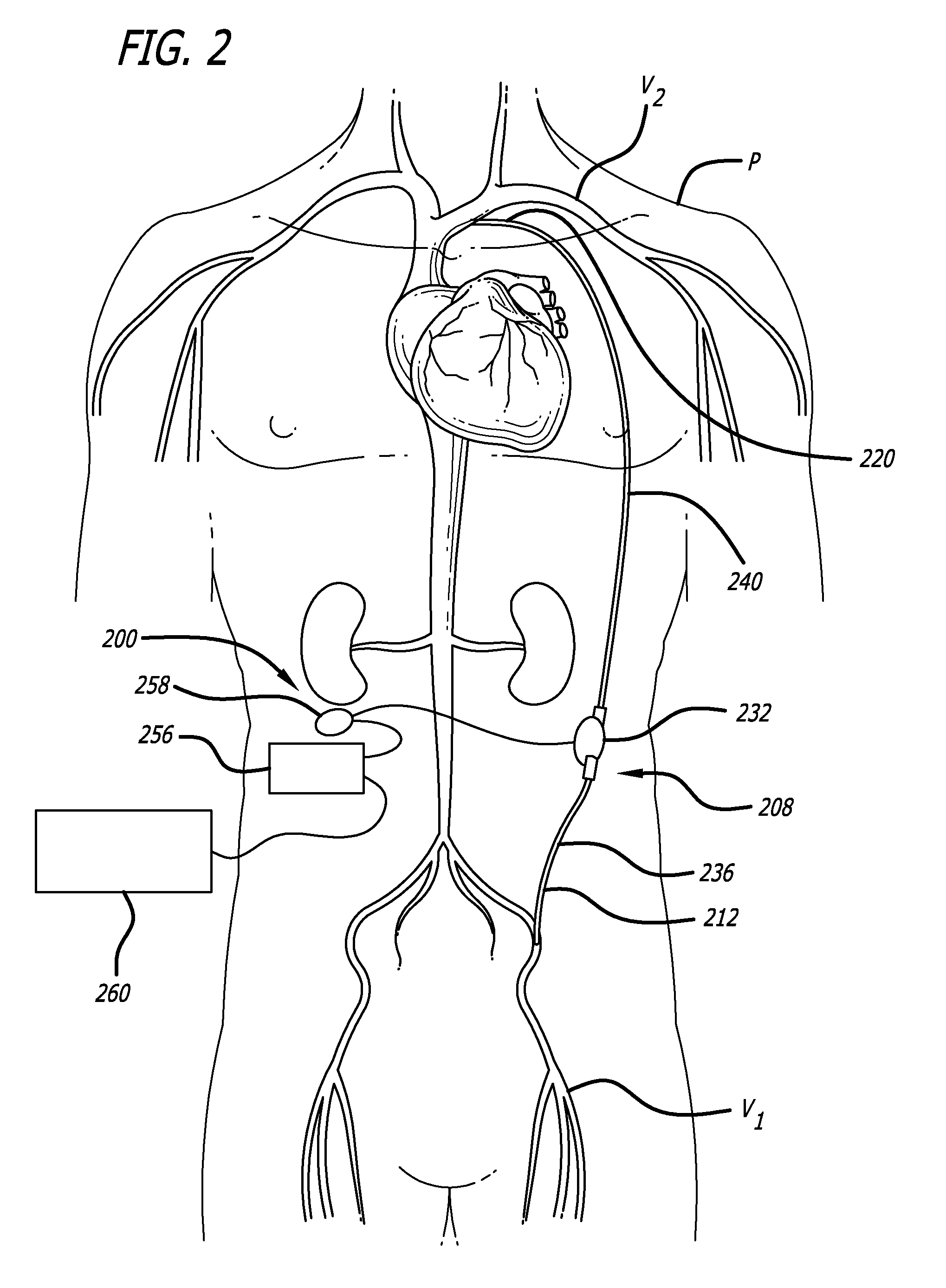
[0007]In one embodiment, a heart assist system is provided that includes an implantable pump, an extracorporeal system, and a communication link. The implantable pump is configured to convey blood between two vascular locations. The extracorporeal system provides power and control signals to the pump. The communication link is coupled with the extracorporeal system and with the pump for conveying information therebetween. The communication link can also convey power to the pump. The communication link comprising includes an implantable portion having a distal end configured to couple with the implantable pump and an extracorporeal portion having a proximal portion configured to couple with the extracorporeal system. Also, the communication link has an isolation portion disposed between the implantable portion and the extracorporeal portion. The isolation portion is configured to minimize the transmission of at least one of movement of and forces from the extracorporeal portion to the implantable portion.
[0008]The isolation portion can be any structure that can be lengthened or change its natural shape to absorb movements or forces that would otherwise be conveyed to a percutaneous site (e.g., a skin puncture through which the communication link extends). For example, a spiral portion can be coiled and uncoiled in response to movement and forces without disrupting the percutaneous site.
[0009]In one embodiment, a communication link is provided for conveying signals between a extracorporeal controller and an implantable pump. The communication link includes a distal end, a proximal end, and an elongate body extending therebetween. The elongate body has a plurality of lumens that extend therethrough. A signal wire extends through each of the lumens. The signal wires convey at least one of power and control signals to the pump. The signal wires also can convey data to the controller. A plurality of contacts is located at the proximal end for placing the communications link in electrical connection with the controller. A plurality of contacts is located at the distal end for connecting the communications link with the pump. The lumens can have a helical arrangement relative to each other to reduce electrical noise and to reduce stress on the wires.
[0010]An apparatus is provided, in another embodiment, for disconnectably connecting a percutaneous signal line to a signal source. The apparatus includes a first connector portion coupled with the percutaneous signal line and a second connector portion electrically coupled with a signal source for conveying control signals between the signal source and the percutaneous signal line. The first connector portion also includes a housing having a distal end and a proximal end. The proximal end has a recess formed therein. The recess comprises a first ramped surface and a second ramped surface positioned distal of the first ramped surface. The second connector portion has a protruding portion extendable into the recess along a connection axis and a compressible member coupled with the protruding portion. The compressible portion extends away from the connection axis by a first amount in the absence of external forces. Distal advancement of the protruding portion in the recess along the connection axis causes the compressible portion to be brought into engagement with the first ramped surface. Further distal advancement of the protruding portion in the recess along the connection axis causes the compressible member to be compressed toward the protruding portion. Still further distal advancement of the protruding portion in the recess along the connection axis causes the compressible member to expand along the length of the second ramped portion.
[0013]In another embodiment, an apparatus for drawing a percutaneous conduit through a tissue tunnel is provided. The apparatus includes a forward portion having a tissue displacing surface and a rearward portion engageable with a proximal end of a percutaneous conduit. A seal is provided that is configured to engage an inside surface of the proximal end of the percutaneous conduit to prevent ingress of bodily tissue and fluid from the tunnel into the proximal end of the percutaneous conduit. The apparatus also includes a tension member for transmitting a pulling force from a proximal end of a tunnel, through the tunnel to at least one of the forward and rearward portions and to the percutaneous conduit.

Problems solved by technology

Heart disease is a growing epidemic in the United States that can lead to heart failure.
In particular, cardiac injury can cause cardiac dysfunction, which results in reduced cardiac output.
One result of reduced cardiac output is endothelial dysfunction, neurohormonal activation, renal impairment, and vasoconstriction.
An increase in systemic vascular resistance can create increased cardiac load which can cause further cardiac dysfunction.
Although there are various treatments proposed and being developed for treating heart failure, such systems are generally limited to the hospital setting or at least require the patient to be very limited in mobility if not completely confined to a bed.

Method used


Image

  • Implantable heart assist system
  • Implantable heart assist system
  • Implantable heart assist system

Examples


Embodiment Construction

[0043]Specific embodiments of the invention will now be described with reference to the accompanying drawings. This invention may, however, be embodied in many different forms and should not be construed as limited to the embodiments set forth herein; rather, these embodiments are provided so that this disclosure will be thorough and complete, and will fully convey the scope of the invention to those skilled in the art. The terminology used in the detailed description of the embodiments illustrated in the accompanying drawings is not intended to be limiting of the invention. In the drawings, like numbers refer to like elements.

[0044]Unless otherwise defined, all terms (including technical and scientific terms) used herein have the same meaning as commonly understood by one of ordinary skill in the art to which this invention belongs. It will be further understood that terms, such as those defined in commonly used dictionaries, should be interpreted as having a meaning that is consis...


PUM


Abstract

A heart assist system having an implantable pump conveying blood between two vascular locations and an extracorporeal system providing power and control signals to the pump. The system also includes a communication link having an implantable portion coupled to the implantable pump, an extracorporeal portion coupled to the extracorporeal system and an isolation portion between the implantable portion and the extracorporeal portion that minimizes the transmission of movement and forces from the extracorporeal portion to the implantable portion.

Description

RELATED APPLICATIONS[0001]This application claims priority to U.S. Provisional Application Ser. No. 61 / 092,714 filed Aug. 28, 2008 entitled Implantable Heart Assist System, which is hereby incorporated herein by reference. Also incorporated herein by reference is U.S. application Ser. No. 11 / 694,761 filed Mar. 30, 2007.FIELD OF THE INVENTION[0002]The present invention relates to a heart assist system and particularly to an implantable heart assist system.BACKGROUND OF THE INVENTION[0003]Heart disease is a growing epidemic in the United States that can lead to heart failure. Heart disease is a progressive, chronic disease with total mortality in 2002 approaching 300,000. AHA 2007 Heart Disease & Stroke Statistics. In the United States alone, 5.2 million people have congestive heart failure with more than one million hospitalizations and 550,000 new diagnosis annually. Id. The total cost of heart failure in the United States is more than $33 billion. Also, US hospital costs for heart ...

Claims


Application Information

Patent Timeline
Patent Type & Authority Applications(United States)
IPC IPC(8): A61M1/10A61N1/08
CPCA61B5/0031A61B2560/0209A61B2560/0214A61M1/10A61M1/122A61M5/14276A61M2205/3507A61M2205/3569A61M1/127A61M60/148A61M60/878A61M60/88A61M60/592A61M60/126
Inventor SCOTT, MICHAELBARE, REX O.MILLER, ROBERTSMITH, JEFFREYMOULDS, ANDREW
Owner TC1 LLC
Learn More