Adaptive pump control during non-invasive blood pressure measurement

a technology of non-invasive blood pressure and pump control, applied in the field of adaptive pump control during non-invasive blood pressure measurement, can solve the problems of wasting time, inability to use a technique, and inability to meet the specific circumstances optimal initial inflation pressur

Inactive Publication Date: 2011-06-23
GENERAL ELECTRIC CO
View PDF9 Cites 30 Cited by
  • Summary
  • Abstract
  • Description
  • Claims
  • Application Information

AI Technical Summary

Problems solved by technology

However, this technique cannot be used if the last determination is not recent, or the patient has been changed, or the instrument has just been powered on.
Without any information about the patient, the initial inflation pressure may not be optimal for the particular circumstances being measu

Method used


Image

  • Adaptive pump control during non-invasive blood pressure measurement
  • Adaptive pump control during non-invasive blood pressure measurement
  • Adaptive pump control during non-invasive blood pressure measurement

Examples


first embodiment

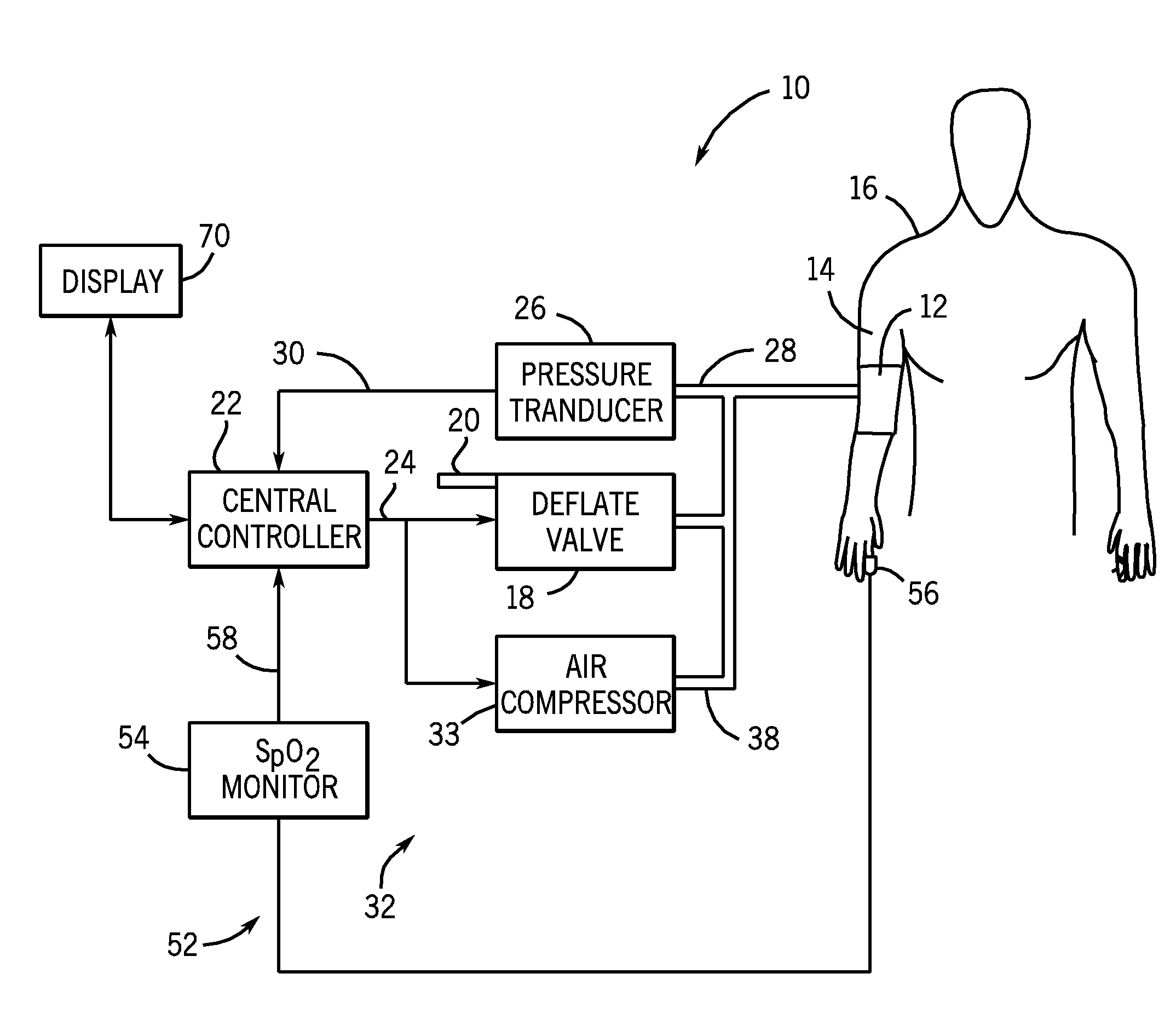
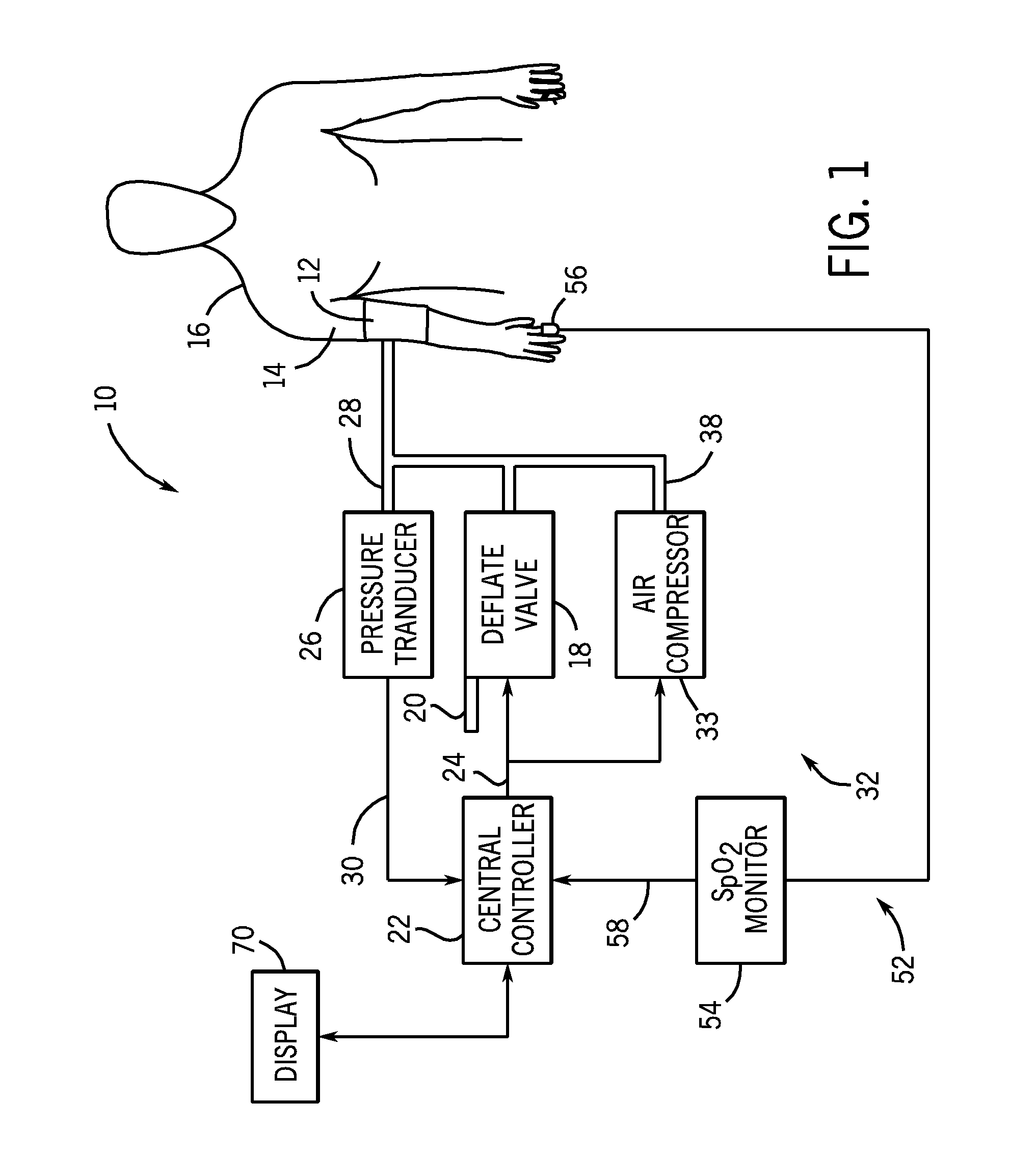
[0032]Referring back to FIG. 1, the system of the first embodiment further includes a pulse monitor 52 for detecting pulse signals from the patient indicative of the patient's heartbeat. In the embodiment of the invention illustrated in FIG. 1, the pulse monitor 52 is a pulse oximeter monitoring system 54 having a sensor that detects a plethysmographic signal from the patient, such as a finger probe 56 positioned on the patient 16 to determine the SpO2 level of the patient 16.

[0033]The pulse oximeter monitoring system 54 generates an SpO2 plethysmographic signal that is provided to the controller 22 of the NIBP monitoring system 10 through a communication line 58. In addition to providing the SpO2 level for the patient, the pulse oximeter monitor 54 provides a plethysmographic waveform 60 (FIG. 3) that includes a series of pulses 62 that each result from a beat of the patient's heart. Since the finger probe 56 is attached to the patient 16 at all times, the pulse oximeter monitor 54...

second embodiment

[0038]In the disclosure, the source of pressurized air 32 can be an air compressor 33 (FIG. 1) that can be operated by the controller to supply pressurized air at various rates. In such an embodiment, the controller provides a control signal to the air compressor to inflate the blood pressure cuff at the rapid inflation rate shown by curve 74.

[0039]Referring back to FIG. 3, the controller inflates the blood pressure cuff at the rapid inflation rate until a change is identified in the plethysmographic pulses 62 as they diminish in size, as identified at point 72. As shown in FIG. 3, the pressure point 72 is slightly below the systolic pressure 48 for the patient.

[0040]In the embodiments shown in FIG. 1, the system rapidly inflates the blood pressure cuff according to curve 74 from approximately 0 mmHg to a pressure between MAP and systolic. The inflation time from the beginning of the inflation cycle to the first pressure 72 will take approximately 5-7 seconds for an adult blood pres...


PUM


Abstract

A method of operating a non-invasive blood pressure (NIBP) monitor having a blood pressure cuff. During operation of the NIBP monitor, the blood pressure cuff is initially inflated at a rapid inflation rate. Once the blood pressure cuff reaches a first pressure, the inflation rate of the blood pressure cuff is reduced from the rapid inflation rate to a measurement inflation rate. The blood pressure cuff continues to inflate at the measurement inflation rate while the NIBP monitor receives signals from the patient. Based upon the signals received from the patient, the controller of the NIBP monitor calculates an initial inflation pressure. The blood pressure cuff is inflated to the calculated initial inflation pressure and inflation is terminated. In this manner, signals received from the patient during inflation are used to calculate the initial inflation pressure to reduce the amount of time required to make a blood pressure measurement.

Description

BACKGROUND OF THE INVENTION[0001]The present disclosure generally relates to a method of controlling a blood pressure cuff inflation to enhance the performance of a non-invasive blood pressure (NIBP) system. More particularly, the present disclosure relates to a method of varying the rate of the inflation of the blood pressure cuff to enhance the measurement of a patient blood pressure.[0002]The oscillometric method of measuring blood pressure involves applying an inflatable cuff around an extremity of a patient's body, such as a patient's upper arm. During the use of a conventional non-invasive blood pressure (NIBP) monitoring system, the cuff is inflated to an initial inflation pressure, which is slightly above the patient's systolic pressure. The cuff is then progressively deflated and a pressure transducer detects the cuff pressure, along with pressure fluctuations or oscillations resulting from the beat-to-beat pressure changes in the artery under the cuff. The data from the pr...

Claims


Application Information

Patent Timeline
IPC IPC(8): A61B5/1455A61B5/021
CPCA61B5/02141A61B5/02225A61B5/1455A61B5/02255A61B5/0225
Inventor DONEHOO, ROBERT F.MEDERO, RICHARD
Owner GENERAL ELECTRIC CO
Why Eureka
Try Eureka