Ultrasonic transducer

a transducer and ultrasonic technology, applied in the field of ultrasonic transducers, can solve the problems of increasing the thickness of the backing layer itself, deteriorating the ultrasonic wave resolution of the ultrasonic diagnostic apparatus, etc., and achieves the effects of reducing the reflected wave, good ultrasonic wave image, and reducing the cost of material

Inactive Publication Date: 2011-06-23
KONICA MINOLTA INC
View PDF2 Cites 22 Cited by
  • Summary
  • Abstract
  • Description
  • Claims
  • Application Information

AI Technical Summary

Benefits of technology

[0017]The ultrasonic transducer according to the present invention effectively reduces the reflected waves by cancelling out the reflected waves, which are the ultrasonic waves that return after having reflected off the end of the backing layer. Thus, the ultrasonic transducer makes it possible to obtain a good ultrasonic wave image without noise.
[0018]In addition, a structure of the ultrasonic transducer according to the present invention allows the backing layer to be thin, and thus the cost in terms of material can be reduced, and the thickness of the ultrasonic transducer can be decreased. Further, in the ultrasonic transducer according to the present invention, heat generation is suppressed, which allows a higher output intensity, and accordingly, an apparent sensitivity is increased.

Problems solved by technology

Due to the effect of the reflected waves described above, noise is superimposed on the received ultrasonic wave signal, resulting in a deteriorated ultrasonic wave resolution of the ultrasonic diagnostic apparatus.
However, such a conventional method has a disadvantage of increasing the thickness of the backing layer itself.

Method used


Image

  • Ultrasonic transducer
  • Ultrasonic transducer
  • Ultrasonic transducer

Examples


embodiment 1

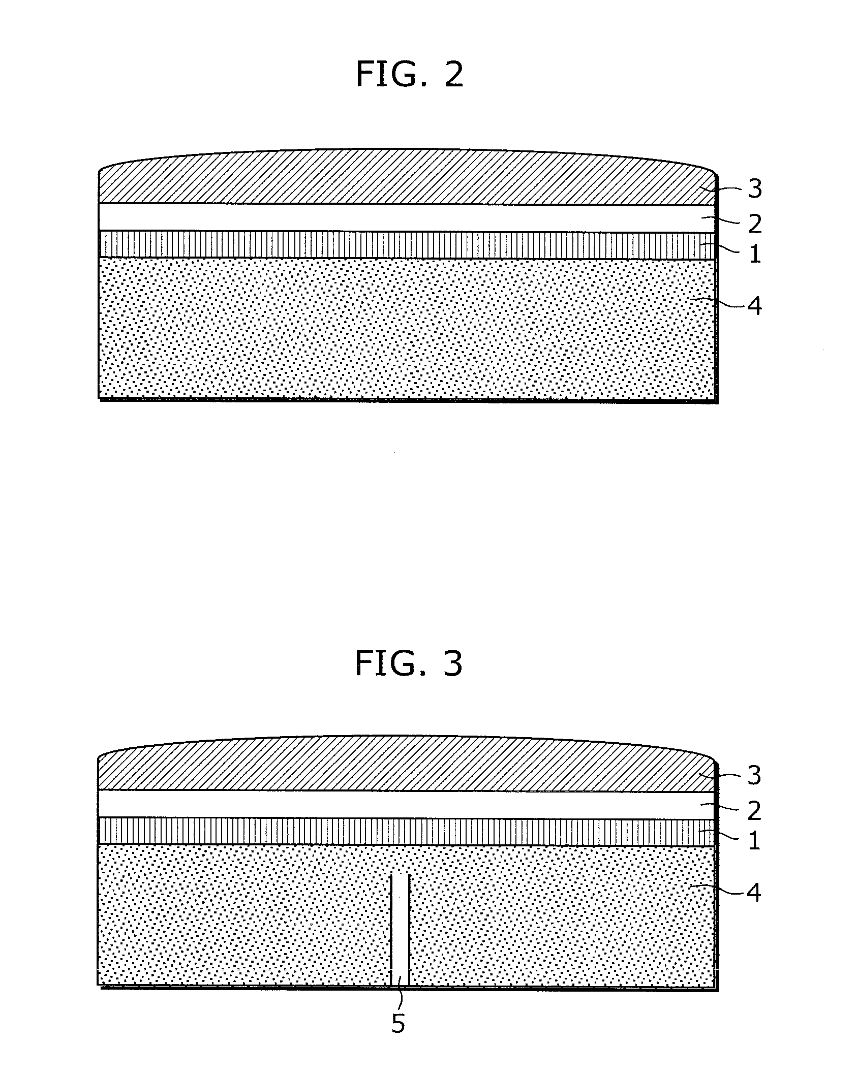
[0036]FIG. 3 is a cross-sectional view of an ultrasonic transducer according to Embodiment 1 of the present invention. As shown in FIG. 3, the ultrasonic transducer according to Embodiment 1 includes a piezoelectric transducer 1, a matching layer 2, an acoustic lens 3, and a backing layer 4.

[0037]As shown in FIG. 3, the ultrasonic transducer according to this embodiment includes an acoustic tube 5 disposed within the backing layer 4. The acoustic tube 5 is formed such that its width is sufficiently small comparing with the wavelength of the ultrasonic waves emitted by the piezoelectric transducer 1, and such that its length causes direct waves of the ultrasonic waves and reflected waves of the ultrasonic waves to cancel out each other.

[0038]For example, when the backing layer 4 is formed of an epoxy resin and it is assumed that the ultrasonic waves f emitted by the piezoelectric transducer 1 is 5 MHz, the wavelength λ in the backing layer 4 may be obtained by Equation 1.

[Math.1]λ=Cf...

embodiment 2

[0041]FIG. 4 is a cross-sectional view of the backing layer 4 according to Embodiment 2 of the present invention. Acoustic tubes 5 are disposed within the backing layer 4.

[0042]FIG. 5 is a cross-sectional view of an exemplary arrangement of the acoustic tubes 5 according to Embodiment 2. Shown in the figure is an example of a backing layer in which the acoustic tubes 5 are arranged on the basis of a quadratic residue sequence. Length Ln of each acoustic tube is determined by a one dimensional quadratic residue sequence shown in Equation 2 below.

[Math.2]Ln=c·n2(modN)2Nωr(Equation2)

[0043]Here, c denotes a speed of sound, N denotes a prime number, and n denotes an integer which varies in a range of 0 to (N−1), and ωr denotes any design frequency. For example when it is assumed that the speed of sound c within the epoxy resin is 5000 m / s, N=11, and ωr=5 MHz, each acoustic tube 5 has, with 45.5 μm as unit length “1”, a length of 1, 4, 9, 5, 3, 3, 5, 9, 4, 1, and 0 respectively.

[0044]The ...

embodiment 3

[0050]In order to realize the backing layer 4 according to Embodiment 3, relief of 250 μm is formed on a board by precision printing based on Embodiment 1. Here, the longitudinal direction of the acoustic tube corresponds to the direction of thickness of ink to be printed. FIG. 14A is a flowchart showing steps for forming the backing layer using screen printing. More specifically, first, a mask for screen printing which is adjusted to have the thickness of 250 μm when dried is formed on a board (S1401). Next, a resist for printing a predetermined pattern is formed (S1402), and then printing is performed by applying material with high impedance as paste, such as metallic conductive paste, onto the board through the mask (S1403). As a result, fine pores are formed on the board. It is to be noted that, here, it is necessary to keep the thickness of the printed paste to be 250 μm or less. When the thickness is 250 μm or less, the rectilinear propagation of the acoustic waves which enter...


PUM

PropertyMeasurementUnit
speedaaaaaaaaaa
lengthaaaaaaaaaa
depthaaaaaaaaaa

Abstract

An ultrasonic transducer includes: a piezoelectric transducer (1) emitting ultrasonic waves; and a backing layer (4) provided in contact with a back side of the piezoelectric transducer (1) and attenuating ultrasonic waves that are emitted toward the back side of the piezoelectric transducer (1) and have an opposite phase to the phase of ultrasonic waves emitted toward a front side of the piezoelectric transducer (1). The acoustic tubes (5) are disposed in the backing layer (4) such that a longitudinal direction of each acoustic tube (5) is in line with a traveling direction of the ultrasonic waves emitted by the piezoelectric transducer (1) toward the front and the back side. The acoustic tubes (5) have mutually different lengths on the basis of a principle of an acoustic wave synthesis, and attenuate in whole or in part the ultrasonic waves emitted by the piezoelectric transducer (1) toward the backing layer (4).

Description

TECHNICAL FIELD[0001]The present invention relates to ultrasonic transducers used for ultrasonic diagnosis.BACKGROUND ART[0002]FIG. 1 shows an exemplary appearance of an ultrasonic transducer and an ultrasonic diagnostic apparatus. As shown in FIG. 1 (a), the ultrasonic transducer is connected to the ultrasonic diagnostic apparatus by a cable. The ultrasonic transducer transmits ultrasonic waves in the direction of an arrow shown in the figure, and receives reflection waves which are reflected from a living body and is in the opposite direction of the arrow. As shown in FIG. 1 (b), the ultrasonic diagnostic apparatus performs image analysis on the reflected waves received by the ultrasonic transducer, and displays on a monitor an image of the inside of the living body obtained through the analysis.[0003]When such an ultrasonic transducer transmits the ultrasonic waves from a piezoelectric transducer, the ultrasonic waves are emitted not only to the front side of a transducer, but al...

Claims


Application Information

Patent Timeline
Patent Type & Authority Applications(United States)
IPC IPC(8): A61B8/14B29C39/12B29C47/00
CPCA61B8/00A61B8/4405B06B1/0677G01N29/0672G10K11/002A61B8/4455
Inventor IKEDA, MASAKOOGURA, TAKASHI
Owner KONICA MINOLTA INC
Why Eureka
Try Eureka