Saw blade and manufacturing method thereof

a manufacturing method and technology for saw blades, applied in the field of saw blades, can solve the problems of large rigidity of saw blades, and large rigidity of tooth points, and achieve the effects of improving the abrasion resistance of saw teeth, reducing cutting resistance, and improving chipping resistan

Inactive Publication Date: 2011-06-30
AMADA CO LTD +1
View PDF34 Cites 34 Cited by
  • Summary
  • Abstract
  • Description
  • Claims
  • Application Information

AI Technical Summary

Benefits of technology

[0105]According to the first aspect to the fifth aspect of the present invention, the rake angle, the tooth angle, the clearance angle, the radius of the chip curler portion, the fan angle of the chip curler portion, and the dimension from the intersection portion of the chip curler portion and the gullet forming sur

Problems solved by technology

This means that rigidity against the cutting resistance is significantly small and strength of the tooth point is small in the case of the band saw blade in comparison with the circular saw blade.
That is, the metal cutting circular saw blade has rigid tooth points and high chipping resistance but has poor cutting performance.
However, the poor cutting performance is compensated by performing forcible incision with the circular saw machine taking advantage of the high rigidity of the body of the circular saw blade.
Accordingly, there is a limitation to increase rigidity of the body of the band saw blade.
In general, cemented carbide is very hard but very brittle.
Thus, the cemented carbide easily causes chipping and it is difficult to form sharp tooth point edges.
In this way, the application individually describes the angles of the tooth point but does not clarify the relationship between the rake angle and the tooth angle.
However, a combination of the rake angle of 15° and the tooth angle of 75° is not practical, because the clearance angle is 0° in this case.
Further, time for making a single cut in a work is longer because the work to be cut is larger than in the case of the circular saw blade.
If high-speed cutting is carried out with a conventional band saw blade, the cutting resistance increases so much that cut deviation or chipping easily occurs because the body of the saw blade is not rigid.
Moreover, high-speed cutting carried out with the conventional band saw blade also causes a problem that gullets are filled and clogged with chips whereby a cut surface becomes coarse.
Here, the rake angle is particularly small and the cutting resistance in high-speed cutting is not sufficiently reduced.
Moreover, a rake surface has a shape like

Method used


Image

  • Saw blade and manufacturing method thereof
  • Saw blade and manufacturing method thereof
  • Saw blade and manufacturing method thereof

Examples


Embodiment Construction

[0115]Embodiments of the present invention will be described below by using the drawings.

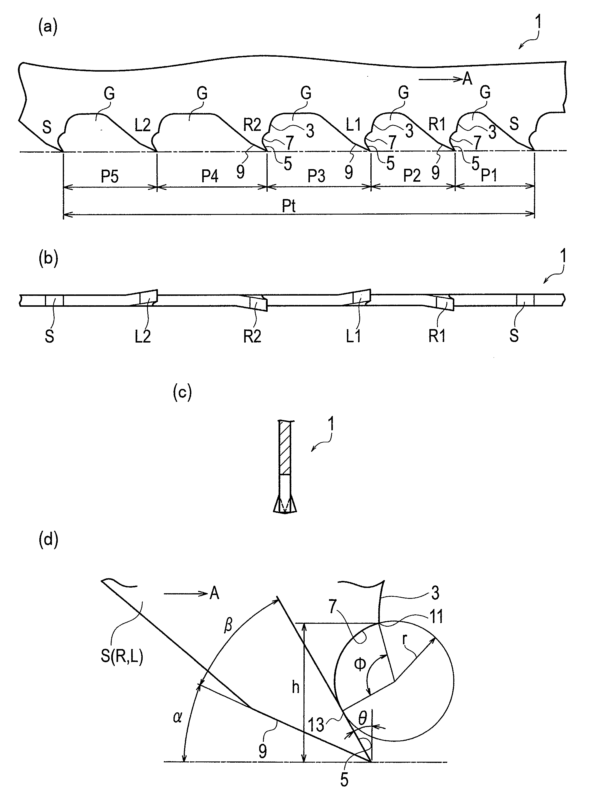
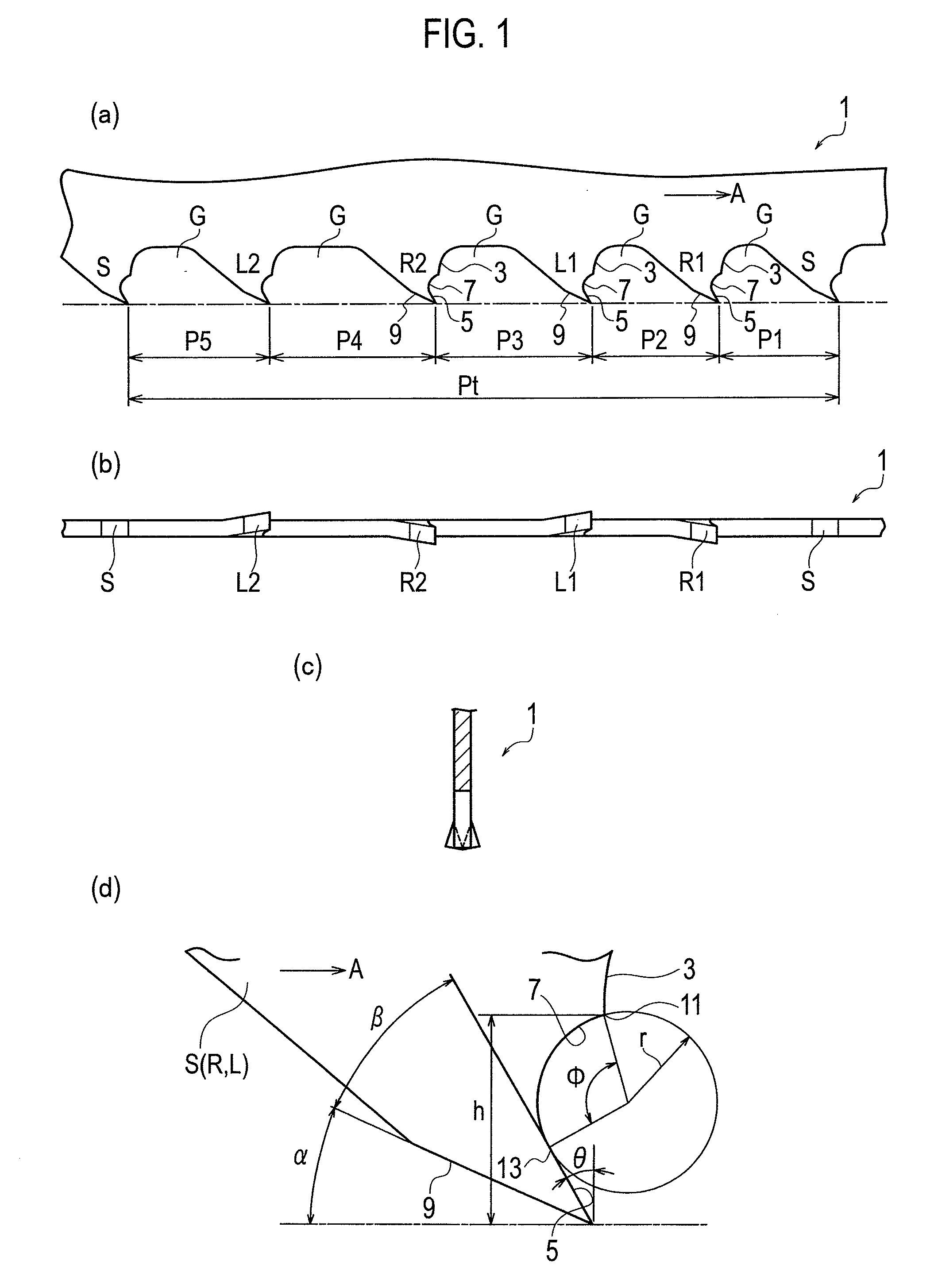
[0116]FIG. 1 conceptually and schematically shows a band saw blade 1 according to an embodiment of the present invention.

[0117]As similar to a general band saw blade, the band saw blade 1 includes a straight tooth S which is not provided with setting in a right-to-left direction viewed from a traveling direction (a direction of an arrow A) of the band saw blade 1, multiple right set teeth R1 and R2 provided with rightward setting, and multiple left set teeth L1 and L2 provided with leftward setting, collectively as one group.

[0118]It is to be noted that the number of the straight teeth S in one group, and the numbers of the right and left set teeth R and L therein are arbitrary, and that the order of layout of the straight teeth S and the right and left set teeth R and L are arbitrary. Moreover, pitches P1 to P5 among the straight teeth S and the right and left set teeth R and L are arbitrary an...


PUM

PropertyMeasurementUnit
Fractionaaaaaaaaaa
Fractionaaaaaaaaaa
Angleaaaaaaaaaa

Abstract

Provided is a saw blade including saw teeth, each of the saw teeth satisfying 17°≦θ≦40°, 35°≦β≦58°, 15°<α, where θ is a rake angle, β is a tooth angle, and α is a clearance angle; a sum of the rake angle θ, the tooth angle β, and the clearance angle α being 90′; a radius r of an arc-shaped chip curler portion 7 in contact with a rake surface 5 of each of the saw teeth being in a range within 10%±4% of any of a saw tooth pitch and an average saw tooth pitch of the saw blade; a fan angle φ of the chip curler portion 7 being in a range within 85°±20°; and a dimension h from an intersection portion 11 of the chip curler portion 7 and a gullet forming surface 3 extending from a tooth bottom side of each of the saw teeth, to a tooth point of each of the saw teeth being in a range within (2r×1.1)±0.2(2r×1.1).

Description

TECHNICAL FIELD[0001]The present invention relates to a saw blade, and more specifically to a saw blade which achieves a reduction in cutting resistance, an improvement in chipping resistance, and an improvement in abrasion resistance in a cutting (severing) process of works.BACKGROUND ART[0002]In general, a saw blade called a bi-metal saw blade is a saw blade in which a blade portion and a body portion are different in material from each other, specifically a saw blade using strong spring steel for the body portion and using a hard material such as cemented carbide, cermets, ceramics or high-speed tool steel for the blade portion. In this industry, the bi-metal saw blade may often indicate a saw blade which uses the high-speed tool steel for the blade portion.[0003]In the same manner as a general cutting bit, a single saw tooth of a saw blade can be defined by a rake angle, a clearance angle, and a tooth angle (an angle formed between a rake surface and a clearance surface) which i...

Claims


Application Information

Patent Timeline
IPC IPC(8): B23D57/00B23D63/00
CPCB23D61/121Y10T83/9319
Inventor OSHIBE, KATSUHIKOTSUJIMOTO, SUSUMU
Owner AMADA CO LTD
Why Eureka
Try Eureka