

Wafer-to-wafer stack with supporting pedestal
- Summary
- Abstract
- Description
- Claims
- Application Information
AI Technical Summary
Benefits of technology
Problems solved by technology
Method used
Image

Examples
Embodiment Construction
[0027]The present invention will now be described more specifically with reference to the following embodiments. It is to be noted that the following descriptions of preferred embodiments of this invention are presented herein for purpose of illustration and description only; it is not intended to be exhaustive or to be limited to the precise form disclosed.
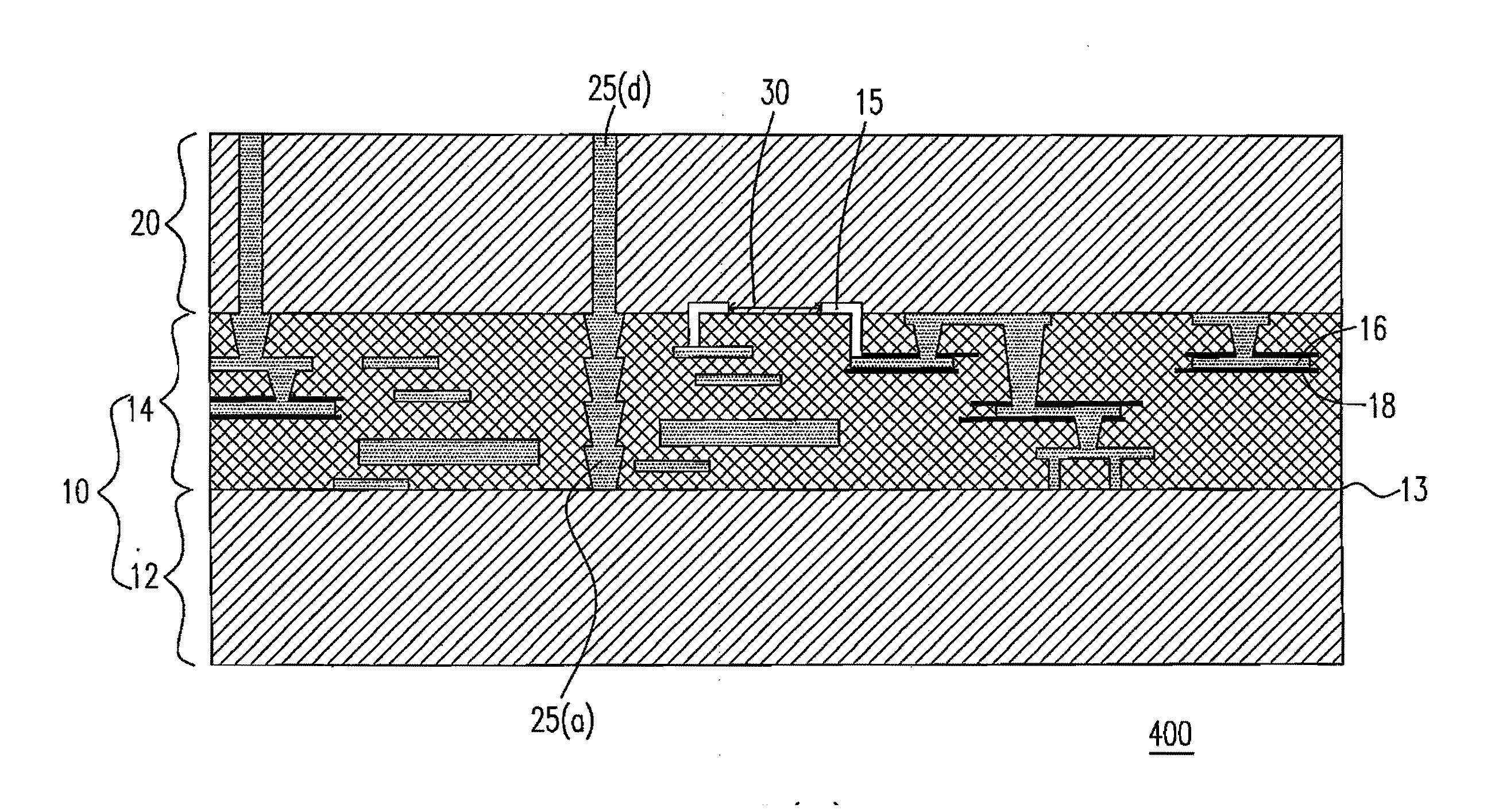
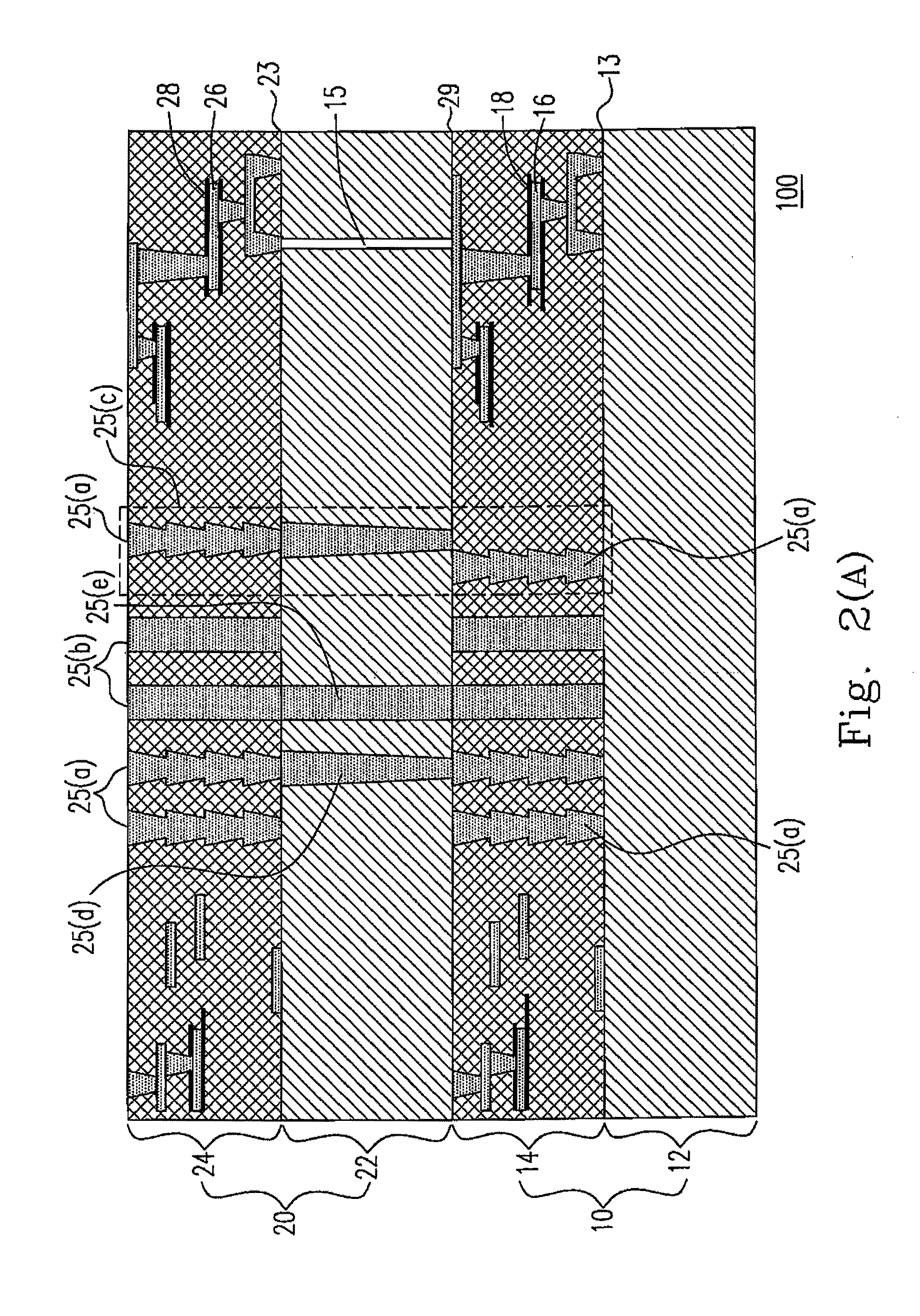
[0028]Please refer to FIGS. 2(A)-2(D), which respectively shows some of the different embodiments of the three dimensional wafer stack according to the present invention. As can be seen from FIG. 2(A), the three dimensional wafer stack 100 according to a first embodiment of the present invention includes a first wafer 10 and a second wafer 20, both of which are arranged face-up, so as to configure the first and the second wafers 10, 20 as a back to face (or back to front) wafer stack. Specifically, the first and the second wafers 10, 20 further include a first and a second substrates 12, 22 as well as a first and a second device ...
PUM
 Abstract
Description
Claims
Application Information