Wireless Energy Transfer System

a technology of energy transfer system and wireless connection, which is applied in the direction of transformer/inductance circuit, basic electric element, inductance, etc., can solve the problems of reducing the service life of the receiver, unable to support millions of users and billions of devices connected to such architectures, and unable to scale or cover great distances, etc., to achieve high potential energy, increase the amplitude, and high concentration of positive charg

Inactive Publication Date: 2011-06-30
GOVERNING DYNAMICS LLC
View PDF17 Cites 404 Cited by
  • Summary
  • Abstract
  • Description
  • Claims
  • Application Information

AI Technical Summary

Benefits of technology

[0015]By modifying or tuning the natural frequency of a transceiver, it becomes possible to transmit over a single frequency or a multitude of frequencies and also receive over the same or different frequencies. Such frequencies (pulse modulated) are overlaid on top of power transmission or a signal which may exist between two or more resonant transceivers and can be inserted or extracted via conductors, induction, or other similar known methods of frequency or optical modulation.
[0016]The Earth is constantly showered with charged particles from the Sun and other stars which create electrostatic pressure on the ionosphere. This charge, which is insulated by the atmosphere, attracts the electrostatic potential in the Earth, and creates a high concentration of positive charge on the surface of the Earth. Moreover, the Earth is a giant dielectric with a very high potential e

Problems solved by technology

The loss factor in most of these systems, which are known as long-haul systems, is 7-10%, and they cost hundreds of millions of dollars to produce.
While some attempts to use other forms of transmission in wired and wireless forms have been tried, there is no system that has been proven to scale or cover great distances or that supports millions of users and billions of devices which could be connected to such architecture.
However, most of the energy associated with the electromagnetic radiation is lost before reaching the receiver and the power that does reach the receiver is extremely low.
However, as in the radiative method, the energy can travel only a distance of a few meters.
It is clear that the cost of transporting fuel has increased drastically in recent years and, as such, it has become much more expensive to produce electricity with all variety of traditional transmission means.
There are significant drawbacks to this method of energy supply.
First of all, it requires an enormous amount of energy, transportation vehicles, and human labor.
These

Method used


Image

  • Wireless Energy Transfer System
  • Wireless Energy Transfer System
  • Wireless Energy Transfer System

Examples


Embodiment Construction

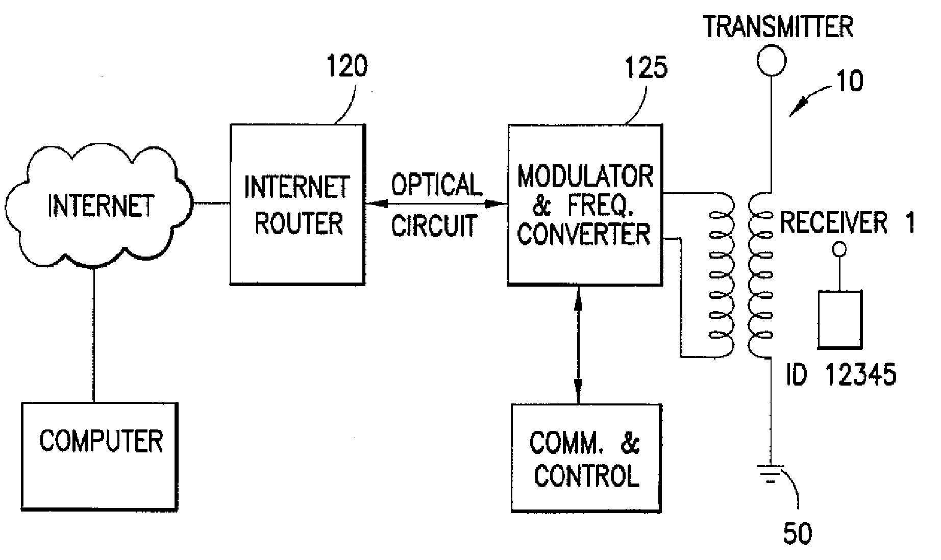
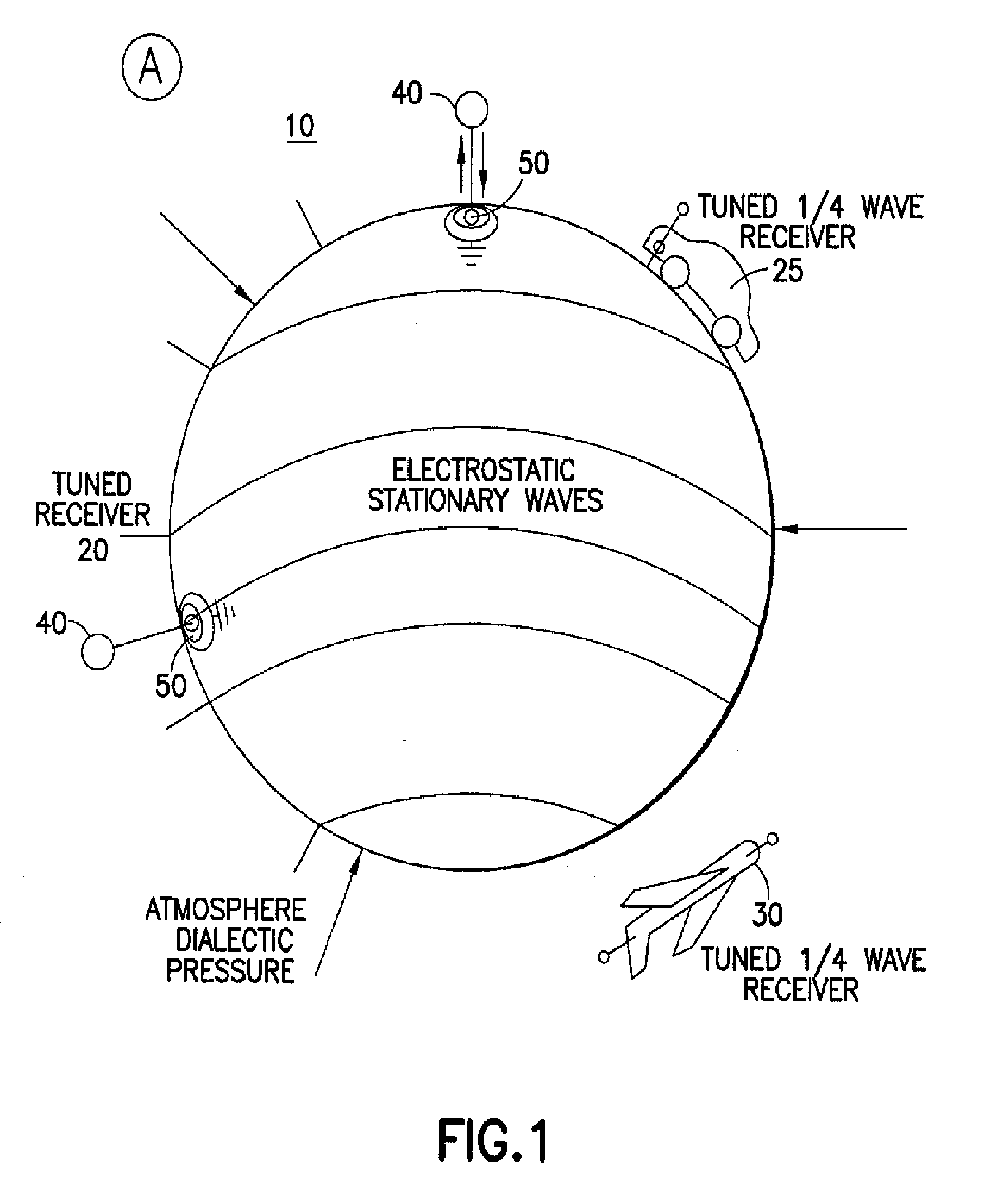
[0026]Disclosed is a system for transmitting power, voice and data without wires or with no more than one connection. The system is also configured to provide communication between an unlimited number of electronic devices, or to connect these devices to an unlimited number of networks that are located externally to the system to thereby enable high speed voice and data communications over a single resonant connection. The disclosed system utilizes at least one transmitter and one receiver, which may have the same or different configurations, such that an induced oscillating electric current which occurs at the resonant frequency of a transmitter connected to Earth or a physical body, such as a lake or plane or other body with defined parameters, can resonate with one or multiple devices tuned to the same frequency.

[0027]FIG. 1 is a schematic block diagram illustrating the general configuration of the system in accordance with the invention. With reference to FIG. 1, a transmitter n...


PUM


Abstract

A system for transmitting power without wires or with no more than one connection, wherein communication is provided between an unlimited number of electronic devices, or to connect these devices to an unlimited number networks that are located externally to the system to thereby enable high speed voice and data communications over a single resonant connection At least one transmitter and one receiver are utilized, which may have the same or different configurations, such that an induced oscillating electπc current, which occurs at the resonant frequency of a transmitter, induces a standing wave The standing wave is tuned and “tapped” by a receiver having a coil or set of plates and receivers that are tuned to oscillate at the same frequency or one of its harmonics and, thus, absorb an electrical current and/or signals at the receiver

Description

CROSS-REFERENCE TO RELATED APPLICATIONS[0001]This application claims priority from U.S. Provisional Application Ser. No. 61 / 091,460 filed Aug. 25, 2008, the content of which is hereby incorporated by reference in its entirety.BACKGROUND OF THE INVENTION[0002]1. Field of the Invention[0003]The present invention relates to the field of power and data distribution and, more particularly, to a method and system for efficient transmission of power and signals using wireless communication devices.[0004]2. Description of the Related Art[0005]Currently, almost all power transmission that occurs operates on a closed circuit where power is generated in a generation facility, carried over wires and is then, with the use of step down transformers, delivered via closed circuit load or motor to an end user. Some systems use a single wire delivery system in which the earth is used as a return, but the generation and delivery system is the same as the previously described system. Such known system ...

Claims


Application Information

Patent Timeline
IPC IPC(8): H02J17/00
CPCH02J17/00H02J50/12H02J50/40H02J50/90H02J50/80
Inventor MASHINSKY, ALEX
Owner GOVERNING DYNAMICS LLC
Why Eureka
Try Eureka