Battery protection system and method thereof

Inactive Publication Date: 2011-06-30
LITE ON ELECTRONICS (GUANGZHOU) LTD +1
7 Cites 12 Cited by

AI-Extracted Technical Summary

Problems solved by technology

Nevertheless, if the battery set is charged directly by a high current that is usually generated during the regenerative braking process of the electric vehicle (regenerative current), such high current will cause the battery set to be charged at an abnormally h...

Benefits of technology

[0019]The present invention prevents a high regenerative current from a load from causing damage to a main battery set when the regenerative current charges the main battery set. The pre...

Abstract

A battery protection method is provided for preventing a main battery set from being damaged by a current from a load, and for lengthening the lifespan of the main battery set. The method includes the steps of: providing an auxiliary battery set; determining whether to recycle energy of the load, and performing a charging mode if affirmative; and transferring energy from the load to the auxiliary battery set when performing the charging mode. The method prevents the main battery set from being damaged due to charging at a high C rate, transfers possible damage due to the high current charging to the auxiliary battery set, lengthens the lifespan of the main battery set, and reduces the overall cost and difficulty of the maintenance of the main battery set by shifting the focus of the maintenance from the main battery set to the auxiliary battery set.

Application Domain

Emergency protective circuit arrangementsDc motor stoppers +8

Technology Topic

EngineeringMain battery +3

Image

  • Battery protection system and method thereof
  • Battery protection system and method thereof
  • Battery protection system and method thereof

Examples

  • Experimental program(1)

Example

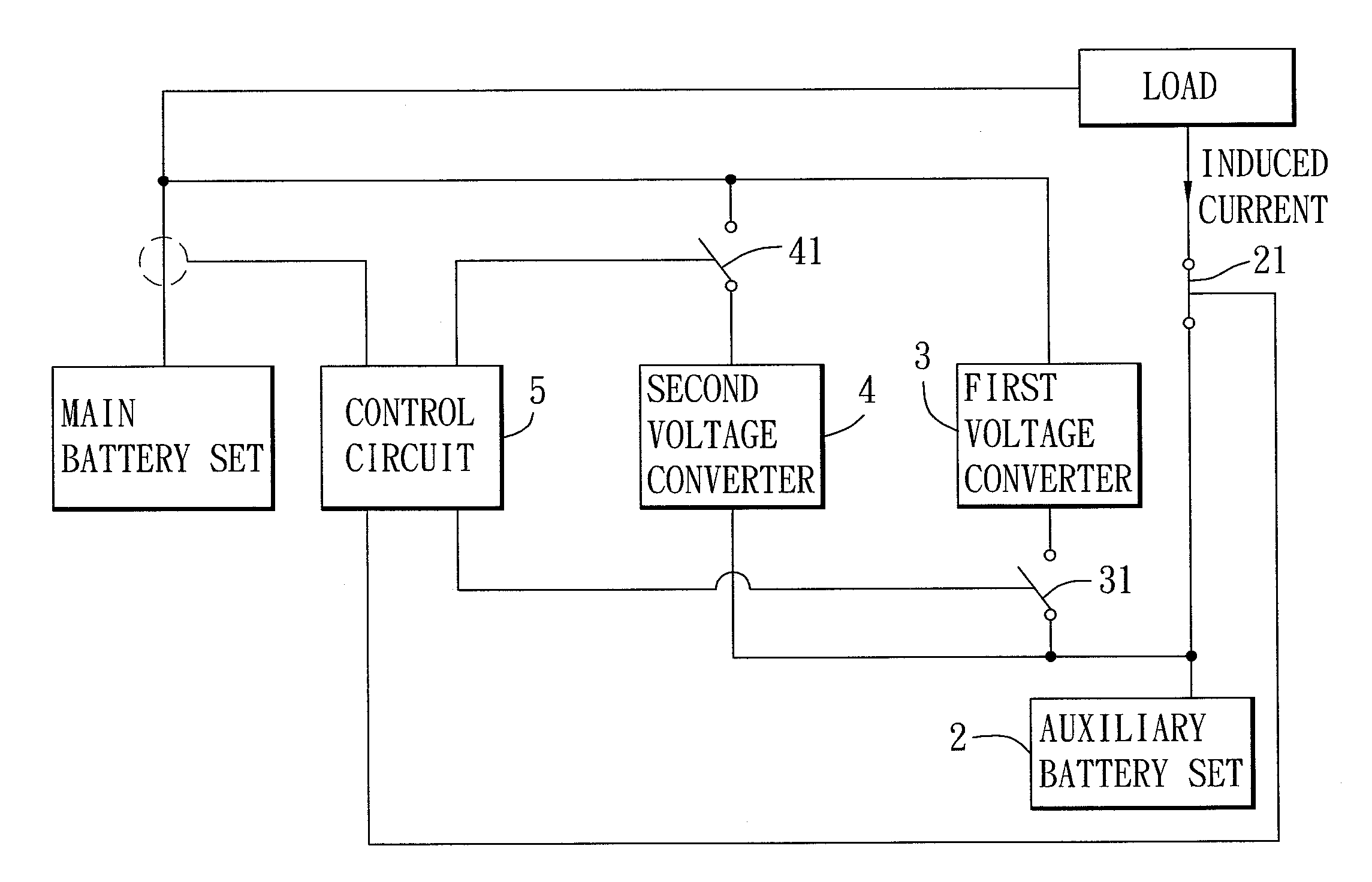
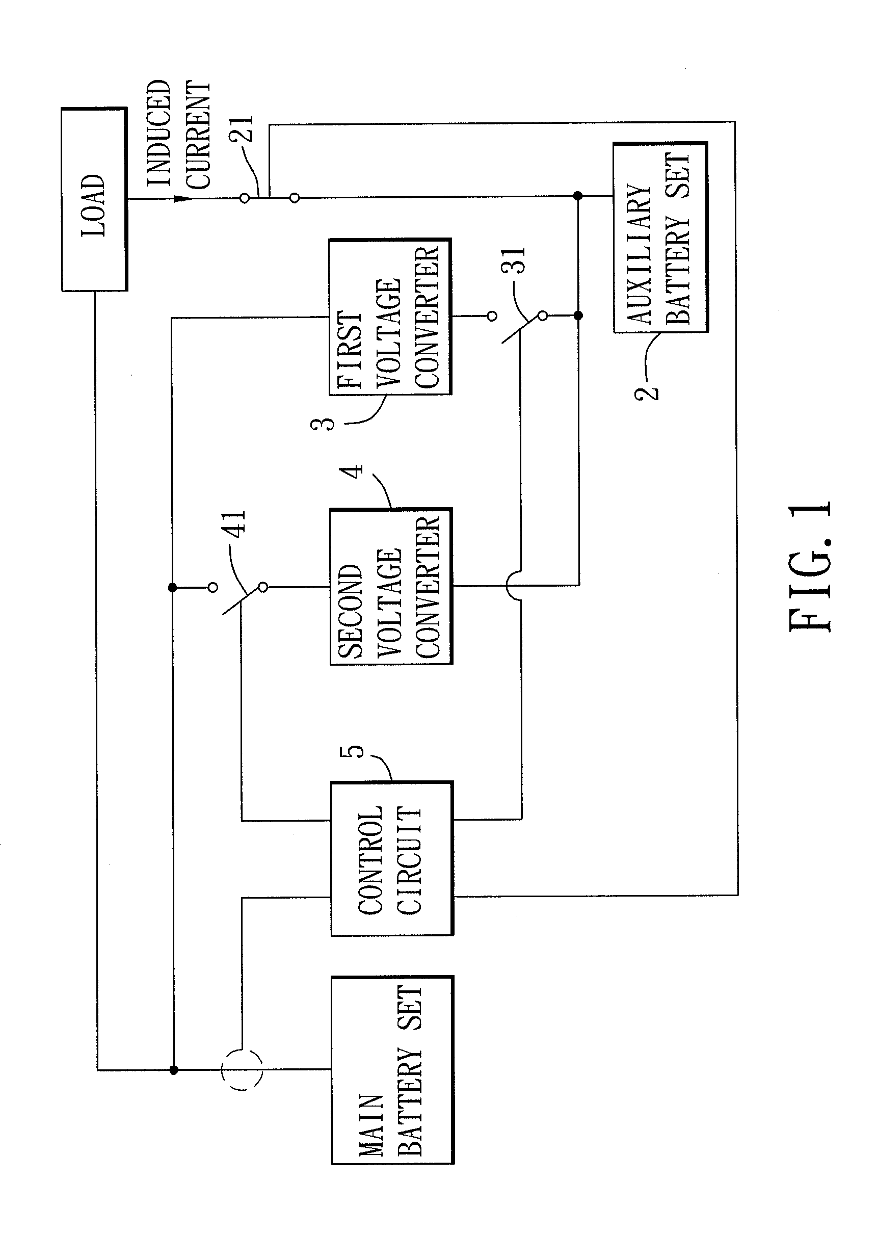
[0025]As shown in FIG. 1, the preferred embodiment of a battery protection system according to the present invention is adapted to be coupled between a main battery set having a plurality of batteries and a set of input/output (I/O) terminals, and a load. The battery protection system is operable in a discharging mode, a charging mode, and a balancing mode. The battery protection system is for preventing a high current from the load (regenerative current) from damaging the main battery set, and for lengthening the lifespan of the main battery set. Furthermore, in the present embodiment, the load is a motor capable of accelerating and decelerating and suitable for use in electric vehicles having regenerative motors. The battery protection system comprises: an auxiliary battery set 2, a first switch 21, a first voltage converter 3, a second switch 31, a second voltage converter 4, a third switch 41, and a control circuit 5.
[0026]The auxiliary battery set 2 is capable of charging and discharging, and includes a set of input/output (I/O) terminals.
[0027]The first switch 21 is electrically connected between the load and the I/O terminal of the auxiliary battery set 2, and is controlled to switch between open (non-conducting) and closed (conducting) states.
[0028]The first voltage converter 3 has an output terminal electrically connected to the I/O terminal of the main battery set, and an input terminal. The first voltage converter 3 is for converting a voltage received by the input terminal thereof to provide a charging current.
[0029]The second switch 31 is electrically connected between the I/O terminal of the auxiliary battery set 2 and the input terminal of the first voltage converter 3. The second switch 31 is controlled to switch between open (non-conducting) and closed (conducting) states.
[0030]The second voltage converter 4 has an output terminal electrically connected to the I/O terminal of the auxiliary battery set 2, and an input terminal. The second voltage converter 4 is for converting a voltage received by the input terminal thereof.
[0031]The third switch 41 is electrically connected between the I/O terminal of the main battery set and the input terminal of the second voltage converter 4.
[0032]Based on an external command, or via detecting the condition of the supplying of power by the main battery set to the load, the control circuit 5 causes the battery protection system to perform a battery protection method.
[0033]As shown in FIG. 2, the battery protection method comprises the steps of:
[0034]10) providing an auxiliary battery set 2;
[0035]20) determining whether to recycle energy of the load, operating in a charging mode if affirmative, and proceed to step 30 if otherwise; and
[0036]30) determining whether to operate in a discharging mode, performing the discharging mode if affirmative, and returning to step 20) if otherwise.
[0037]In step 20), the control circuit 5 operates in the charging mode when it is detected that the motor performs braking and generates recyclable energy.
Charging Mode:
[0038]As shown in FIG. 1, when the main battery set provides electricity to the load, and the load generates an induced current, the control circuit 5 will perform the charging mode, and will control the first switch 21 such that the induced current is able to charge the auxiliary battery set 2 via the first switch 21, thereby the energy of the load to be recycled is transferred to the auxiliary battery set 2.
[0039]By arranging the auxiliary battery set 2 to serve as a buffer between the load and the main battery set, possible damage due to the induced current from the load is transferred from the main battery set to the auxiliary battery set 2, thereby preventing the induced current from damaging the main battery set when the magnitude of the induced current is large.
Discharging Mode:
[0040]As shown in FIG. 3, when the main battery set is not providing energy to the load and is in an idle state, the control circuit 5 will perform the discharging mode in which the control circuit 5 controls the first and third switches 21, 41 to open, and the second switch 31 to close so as to electrically connect the input terminal of the first voltage converter 3 and the I/O terminal of the auxiliary battery set 2.
[0041]In the meantime, the first voltage converter 3 will convert the output voltage of the auxiliary battery set 2 to conform with the input voltage of the main battery set and will generate a charging current for charging the main battery set, thereby transferring energy of the auxiliary battery set 2 to the main battery set, wherein the charging current has a magnitude such that the main battery set is charged by a trickle current.
[0042]Moreover, in the present embodiment, the first voltage converter 3 is a boost DC-DC converter for boosting the output voltage of the auxiliary battery set 2 to conform with the input voltage of the main battery set.
[0043]It is to be noted that the full charge capacity (FCC) of the main battery set decreases with an increase in the number of uses. The decrease in the FCC includes an irreversible loss and a reversible loss. The irreversible loss is caused by wearing of active material, and hence cannot be recovered. The reversible loss is caused by improper charging and discharging processes (e.g., high-current discharging and high-current charging), which causes the arrangement of the active material in the battery to be irregular, and subsequently lessens the amount of reusable active material. By virtue of trickle charging, the active material in the battery is given enough time to be rearranged regularly during the migration, thereby reducing the reversible loss, slowing down the aging process of the battery, and lengthening the lifespan of the main battery set.
[0044]The battery protection method further comprises the step of
[0045]40) determining whether to perform a balancing mode, operating in the balancing mode if affirmative, and returning to step 20) if otherwise.
Balancing Mode:
[0046]The main battery set includes a plurality of batteries. Because the batteries may have different charging and discharging capacities, charging conversion efficiencies, and initial capacities, the voltages of the batteries will be different after repeated charging and discharging processes. At this time, it is required to balance the batteries. The control circuit 5 detects voltage of each of the batteries, and compares the voltage of each of the batteries with a reference voltage, thereby determining if the voltage of any of the batteries is higher than the reference voltage. If affirmative, the control circuit 5 will perform the balancing mode. Besides, the control circuit 5 can also be controlled to perform the balancing mode based on an external command.
[0047]As shown in FIG. 4, while performing in the balancing mode, the control circuit 5 will control the first and second switches 21, 31 to open, and the third switch 41 to close so as to electrically connect the I/O terminal of the main battery set and the input terminal of the second voltage converter 4. Subsequently, the second voltage converter 4 converts the output voltage of the main battery set to conform with the input voltage of the auxiliary battery set 2 so as to transfer energy of batteries of the main battery set, that have voltages higher than the reference voltage, to the auxiliary battery set 2. The transfer of energy continues until the voltages of the batteries are all equal to the reference voltage, i.e., the voltages of the batteries of the main battery set are balanced, thereby preventing the main battery set from being damaged due to over-charging or over-discharging (or even explosion) during subsequent charging and discharging processes.
[0048]Furthermore, in the present embodiment, the second voltage converter 4 is a buck DC-DC converter for bucking the output voltage of the main battery set to conform with the input voltage of the auxiliary battery set 2.
[0049]In summary, the present invention has the following advantages.
[0050]First, the present invention achieves the effects of charging and maintaining the main battery set by trickle charging the main battery set using the auxiliary battery set 2.
[0051]Second, the auxiliary battery set 2 is arranged to serve as a buffer between the load and the main battery set such that the auxiliary battery set 2 is charged by an induced current from the load, generates a charging current having a relatively small magnitude (trickle current), and provides the charging current to the main battery set. Therefore, the arrangement of the auxiliary battery set 2 prevents the induced current from the load, which has a relatively large magnitude, from causing damage to the main battery set, and transfers the possible damage due to the induced current from the main battery set to the auxiliary battery set 2. Hence, the present invention can slow down the ageing process of the main battery set. Moreover, since the cost and the difficulty of maintenance of the auxiliary battery set 2 are lower and easier than those of the main battery set, the present invention reduces the overall cost and the difficulty of the maintenance of the main battery set by shifting the focus of the maintenance from the main battery set to the auxiliary battery set 2.
[0052]Third, the control circuit 5 of the present invention transfers energy of batteries of the main battery set, that have relatively higher voltages, to the auxiliary battery set 2 so as to balance the voltages of the batteries.
[0053]While the present invention has been described in connection with what is considered the most practical and preferred embodiment, it is understood that this invention is not limited to the disclosed embodiment but is intended to cover various arrangements included within the spirit and scope of the broadest interpretation so as to encompass all such modifications and equivalent arrangements.

PUM

no PUM

Description & Claims & Application Information

We can also present the details of the Description, Claims and Application information to help users get a comprehensive understanding of the technical details of the patent, such as background art, summary of invention, brief description of drawings, description of embodiments, and other original content. On the other hand, users can also determine the specific scope of protection of the technology through the list of claims; as well as understand the changes in the life cycle of the technology with the presentation of the patent timeline. Login to view more.

Similar technology patents

PLC opto-isolator driving circuit and resistance loop device of MOS gate

ActiveCN103337839Ahigh currentshorten discharge time
Owner:STATE GRID CORP OF CHINA +2

Tunneling transistor with asymmetric gate

ActiveUS20150021654A1high current
Owner:NATIONAL TSING HUA UNIVERSITY

Tunneling field effect transistor and forming method thereof

PendingCN110718463Agood electrical conductivityhigh current
Owner:SEMICON MFG INT (SHANGHAI) CORP +1

Assorted power generation device applied to petrol-electric integrated vehicles refitted from multiple fuel vehicles

InactiveCN109720218Ahigh currentReasonable device design
Owner:吉林省鸿途新能源有限责任公司

Semiconductor device and manufacturing method thereof

ActiveCN108878513Ahigh current
Owner:VANGUARD INTERNATIONAL SEMICONDUCTOR CORPORATION

Classification and recommendation of technical efficacy words

  • high current

System and method for generating radio frequency energy

ActiveUS20070225698A1high current
Owner:COVIDIEN AG

Weld schedule for resistance spot welding of aluminum alloy workpieces

ActiveUS20130048613A1decrease welder throughputhigh current
Owner:GM GLOBAL TECH OPERATIONS LLC

Systems and methods for rechargeable battery collector tab configurations and foil thickness

ActiveUS20090305120A1minimize resistancehigh current
Owner:BASVAH

Spherical neutron generator

InactiveUS7139349B2high currenthigh brightness
Owner:RGT UNIV OF CALIFORNIA
Why Eureka
Try Eureka