System for monitoring oil level and detecting leaks in power transformers, reactors, current and potential transformers, high voltage bushings and the like

a technology for monitoring oil level and leakage detection, which is applied in the direction of liquid/fluent solid measurement, 2d-image generation, instruments, etc., can solve the problems of reducing oil level, increasing and reducing oil level, and forced shut down of equipment for removal of oil

Active Publication Date: 2011-06-30
SANTOS EDUARDO PEDROSA
View PDF14 Cites 71 Cited by
  • Summary
  • Abstract
  • Description
  • Claims
  • Application Information

AI Technical Summary

Benefits of technology

[0018]Aware of the state of art, its inconveniences and limitations, the inventor, active in the segment of matters in hand, studies and research, created the “SYSTEM FOR MONITORING OIL LEVEL AND DETECTING LEAKS IN POWER TRANSFORMERS, REACTORS, CURRENT AND POTENTIAL TRANSFORMERS, HIGH VOLTAGE BUSHINGS AND T

Problems solved by technology

However, temperature variations during equipment operation due to variations in ambient temperature and heating caused by the electric current, make the oil dilate and contract, thus making its volume vary and increasing and reducing oil level.
The state of the art for the oil level indication system presents some disadvantages observed in practice, which are:Because it is a mechanically activated system, it is subject to mechanical failures such as jamming of the mechanism;In order to prevent mechanical failures, it is necessary to have preventive maintenance for lubrication, for example;With the up and down movement of the oil level, the rubber of the membrane or bag may present undulations or folds in which the float may get caught, leading to the imprecise indication of oil level;In extreme cases, the above described fact may cause the float and/or its rod to perforate the membrane or bag, put

Method used


Image

  • System for monitoring oil level and detecting leaks in power transformers, reactors, current and potential transformers, high voltage bushings and the like
  • System for monitoring oil level and detecting leaks in power transformers, reactors, current and potential transformers, high voltage bushings and the like
  • System for monitoring oil level and detecting leaks in power transformers, reactors, current and potential transformers, high voltage bushings and the like

Examples


Embodiment Construction

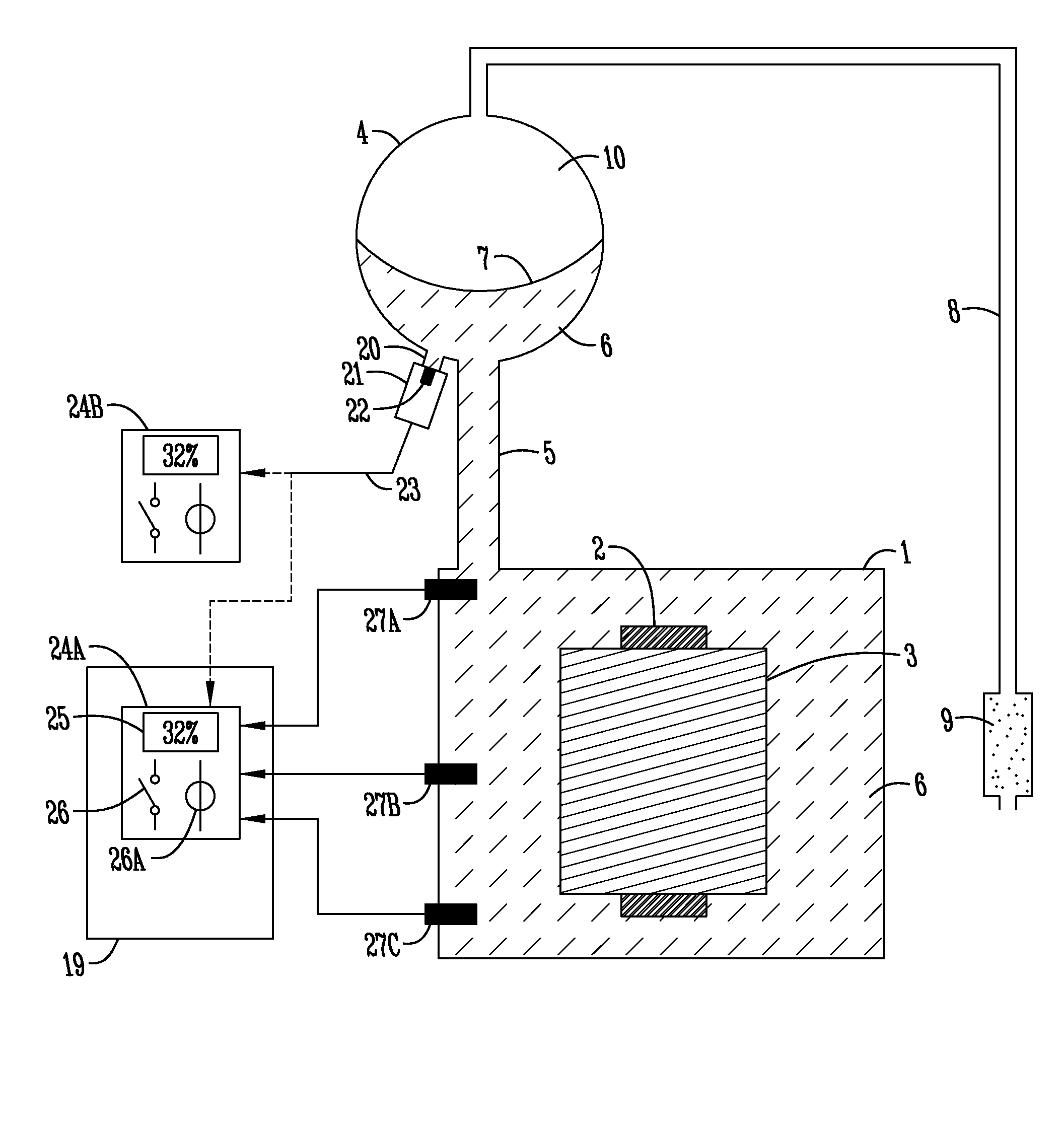
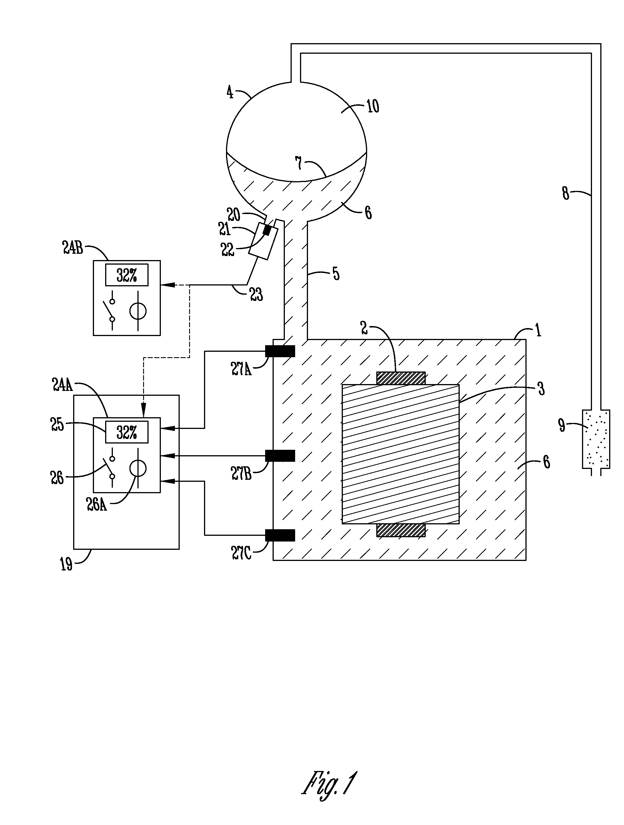
[0031]The “SYSTEM FOR MONITORING OIL LEVEL AND DETECTING LEAKS IN POWER TRANSFORMERS, REACTORS, CURRENT AND POTENTIAL TRANSFORMERS, HIGH VOLTAGE BUSHINGS AND THE LIKE”, for measuring and monitoring insulating oil levels of transformers and similar equipment, using an oil level monitor (24A, 24B) to which a pressure sensor (21), to measure internal oil column pressure (6), and a temperature sensor (22), arranged to measure oil temperature (6) in the expansion tank (4), are connected, so that the level monitor (24A, 24B) calculates oil column height, which corresponds to the oil level, from the oil pressure and takes into account the change in oil density with temperature, precisely indicating the oil level (6) on the display (25).

[0032]The system, as shown in FIG. 1, is comprised of an electronic pressure sensor (21) installed in an access opening (20), which normally already exists in the lower part of the expansion tank (4) for draining. The sensor (21) measures oil pressure (6) at...


PUM


Abstract

System for monitoring oil level and detecting leaks in power transformers, reactors, current and potential transformers, high voltage bushings and the like, notably for a system that through the use of sensors and other electronic components measures and monitors transformers and similar equipment in real time, filled with insulating oil, with greater precision and without need for floats or mobile mechanical parts, while presenting countless facilities in the sense of making level monitoring more reliable and safer, highlighting the level error calculations, oil leak detection alarm, excess oil detection alarm during the equipment filling process and calculation of tendencies of evolution for levels among other facilities.

Description

FIELD OF THE INVENTION[0001]This petition for a patent is for an original “SYSTEM FOR MONITORING OIL LEVEL AND DETECTING LEAKS IN POWER TRANSFORMERS, REACTORS, CURRENT AND POTENTIAL TRANSFORMERS, HIGH VOLTAGE BUSHINGS AND THE LIKE”; namely a system that uses sensors and other electronic components to measure and monitor, in real time, transformers and similar equipment filled with insulating oil with greater precision and without any need for floats or other movable, mechanical parts, while also presenting countless facilities in terms of making level monitoring more reliable and safer, highlighting level error calculations, an alarm when detecting oil leaks, or detecting excess oil during the equipment filling process and the calculation of tendencies of evolution for levels, among other facilities.BACKGROUND OF THE INVENTION[0002]Power transformers and reactors are pieces of equipment widely used in medium, high and extra-high voltage electric power generation, transmission and di...

Claims


Application Information

Patent Timeline
IPC IPC(8): G08B21/00G06T11/20
CPCG01F23/0076G01F23/185G01F23/18G01F23/804
Inventor SANTOS, EDUARDO PEDROSA
Owner SANTOS EDUARDO PEDROSA
Why Eureka
Try Eureka