Using output drop detection pulses to achieve fast transient response from a low-power mode

Active Publication Date: 2011-06-30
ACTIVE SEMI
View PDF13 Cites 39 Cited by
  • Summary
  • Abstract
  • Description
  • Claims
  • Application Information

AI Technical Summary

Benefits of technology

[0013]Other primary current pulses, however, are of a substantially smaller peak amplitude and are referred to here as “output drop detection pulses”. These output drop detection pulses are used, not for energy transfer or VOUT regulation, but rather are used to determine whether the output voltage VOUT has dropped. An output drop detection pulse is of such a small peak amplitude that if VOUT does not decrease, then a secondary flyback current induced in the secondary winding as a consequence of the output drop detection pulse is not of adequate magnitude to always forward bias the output diode. If, on the other hand, VOUT decreases, then the secondary flyback current due to an output drop detection pulses does cause the output diode to be forward biased. The PSR controller integrated circuit of the PSR power supply detects an auxiliary-referred voltage signal and from this voltage signal determines whether the output diode was forward biased as a result of an output drop detection pulse. In one example, if VOUT is determined to have dropped in this manner, then the PSR power supply is made to stop operating in a standby mode and is made to begin operating in a higher power normal operating mode.
[0014]In a second novel aspect, a PSR power supply includes a low c

Problems solved by technology

The secondary side regulator (SSR) power supply 1 of FIG. 1 operates satisfactorily well in many applications, but it can be undesirably expensive in ultra low cost applications.
Such a power supply generally has poor low-power standby mode transient response.
If the load on the power supply output were suddenly to increase, and the next samp

Method used


Image

  • Using output drop detection pulses to achieve fast transient response from a low-power mode
  • Using output drop detection pulses to achieve fast transient response from a low-power mode
  • Using output drop detection pulses to achieve fast transient response from a low-power mode

Examples


Embodiment Construction

[0034]Reference will now be made in detail to some embodiments of the invention, examples of which are illustrated in the accompanying drawings.

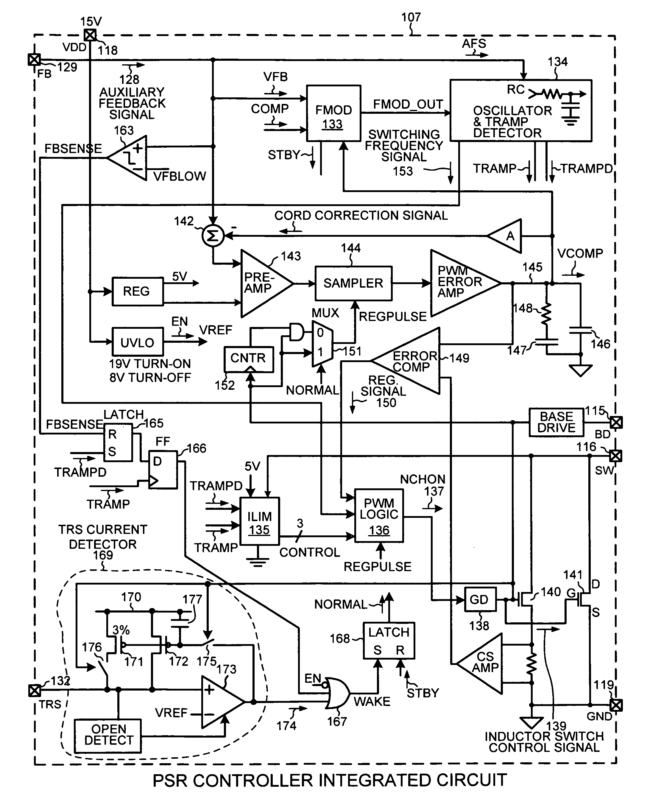
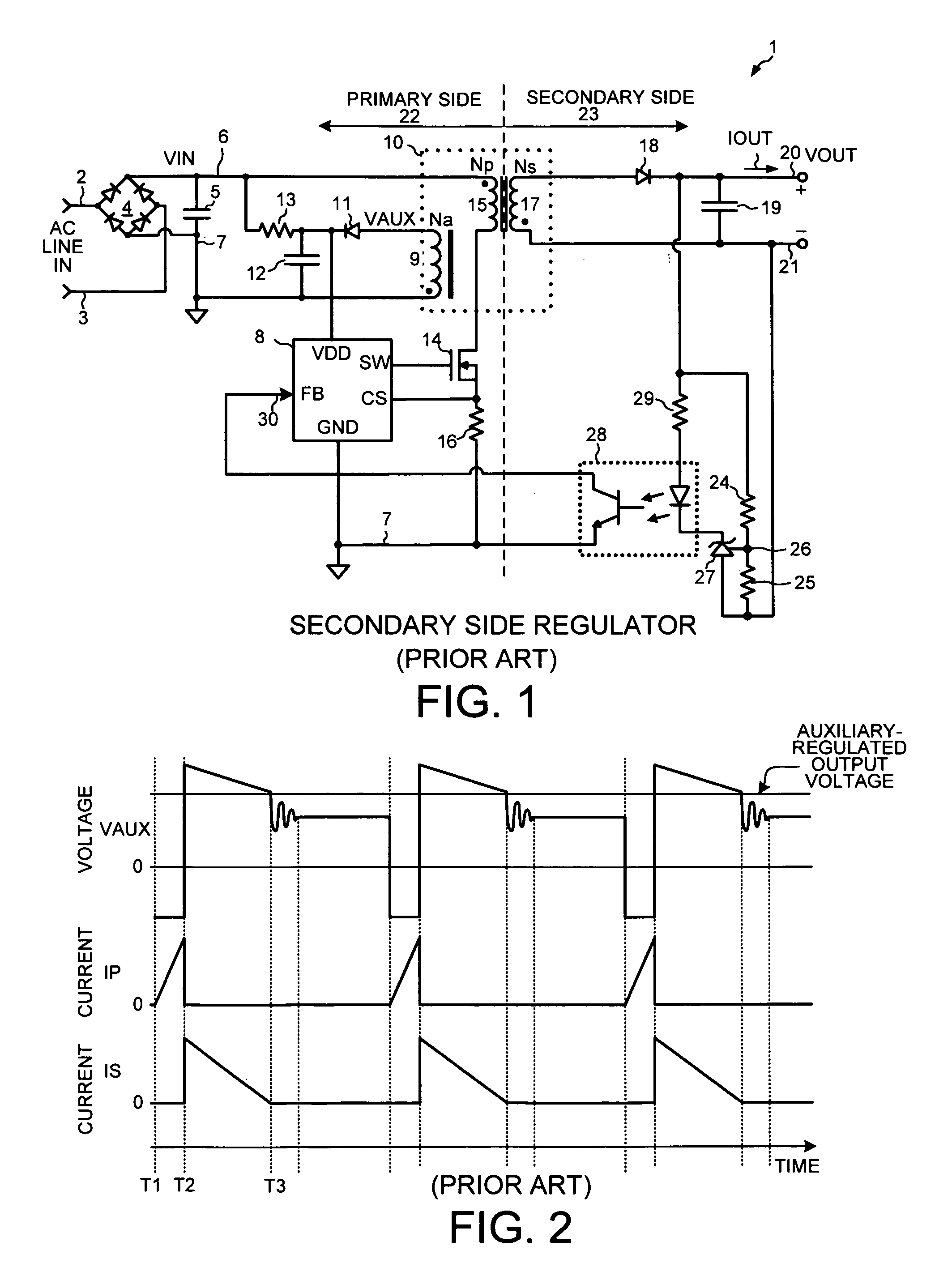
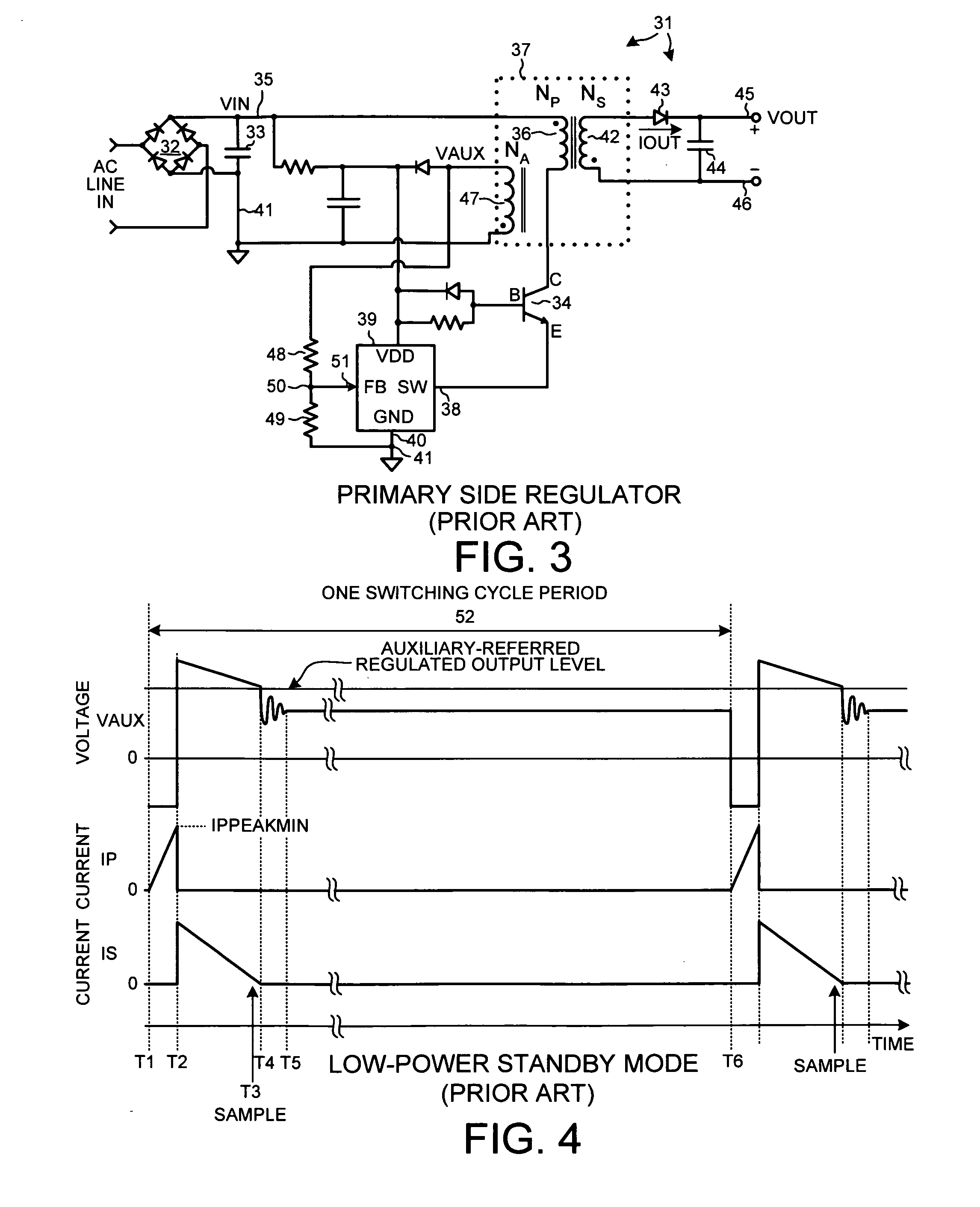
[0035]FIG. 5 is a block diagram of a Primary Side Regulation (PSR) flyback power supply 100 in accordance with one novel aspect. An alternating current (AC) 110-240 volt line voltage on input terminals 101 and 102 is rectified by a full wave bridge rectifier 103 and an associated smoothing capacitor 104 so that a rectified and smoothed rough DC voltage is present between the first and second input nodes 105 and 106. The voltage on first input node 105 is also referred to as the “input line voltage” or “line input voltage” (VIN). The voltage on second input node 106 is referred to as ground potential.

[0036]A PSR controller integrated circuit 107 is powered by a DC voltage supplied by auxiliary winding 108 of a transformer 109 and a rectifier involving diode 110 and capacitor 111. Supply current from node 117 is received onto PSR controller in...


PUM


Abstract

In a first aspect, in a Primary Side Regulation (PSR) power supply, some primary current pulses are used to forward bias an output diode such that an auxiliary winding voltage can be properly sampled after each pulse. The samples are used to regulate the power supply output voltage (VOUT). Other primary current pulses, however, are of a smaller peak amplitude. These pulses are not used for VOUT regulation, but rather are used to determine whether the VOUT has dropped. In a second aspect, a transient current detector circuit within the PSR controller integrated circuit detects whether an optocoupler current has dropped in a predetermined way. If the TRS current detector detects that the optocoupler current has dropped, then the power supply stops operating in a sleep mode and is made to operate in another higher power operating mode in which the power supply switches.

Description

TECHNICAL FIELD[0001]The present disclosure relates generally Primary-Side Regulation (PSR) power supplies and PSR controller integrated circuits.BACKGROUND INFORMATION[0002]FIG. 1 (Prior Art) is a block diagram of a Secondary-Side Regulation (SSR) flyback power supply 1. An alternating current (AC) 110-240 volt line voltage on input terminals 2 and 3 is rectified by a full wave bridge rectifier 4 and an associated smoothing capacitor 5 so that a rectified and smoothed rough DC voltage is present between the first and second input nodes 6 and 7. The voltage on first input node 6 is also referred to as the “input line voltage” or “line input voltage” (VIN). A SSR controller integrated circuit 8 is powered by a DC voltage supplied by auxiliary winding 9 of a transformer 10 and a rectifier involving diode 11 and capacitor 12. Immediately after startup when the rectifier has not yet switched an adequate number of times to charge capacitor 12, start up power for integrated circuit 8 is r...

Claims


Application Information

Patent Timeline
IPC IPC(8): H02M7/217
CPCH02M3/33507Y02B70/16H02M2001/0032H02M3/33523H02M1/0032Y02B70/10
Inventor HUYNH, STEVEN
Owner ACTIVE SEMI
Why Eureka
Try Eureka