Disaster recovery using local and cloud spanning deduplicated storage system

Inactive Publication Date: 2011-06-30
RIVERBED TECH INC
View PDF11 Cites 187 Cited by
  • Summary
  • Abstract
  • Description
  • Claims
  • Application Information

AI Technical Summary

Benefits of technology

In an embodiment, two or more spanning storage interfaces may be used in a disaster recovery application. Disaster recovery application may be used to provide redundant data access to storage clients in the event that the storage clients and/or cloud spanning storage interface at a first network location are disabled, destroyed, or otherwise inaccessible or inoperable. A disaster recovery application includes at least first and second spanning storage interfaces at first and second network locations. The second spanning storage interface is provided for at least disaster recovery operations. The second spanning storage interface includes second local storage for improving data access performance. A copy of the local cache of the first spanning storage interface is transferred to the second local storage while the first network location is operating. In the event of a disaster affecting the first network location, the second spanning storage interface can provide data access to the first network location

Problems solved by technology

The CPU and I/O requirements for supporting an extremely large data deduplicating storage are significant, and are difficult to satisfy through vertical scaling of a single device.
As a result, prior spanning storage interface may impose severe throughput, latency, and other performance penalties on storage clients.
Additionally, performance considerations limit the amount and types of optimizations and compression applied by prior

Method used


Image

  • Disaster recovery using local and cloud spanning deduplicated storage system
  • Disaster recovery using local and cloud spanning deduplicated storage system
  • Disaster recovery using local and cloud spanning deduplicated storage system

Examples


Embodiment Construction

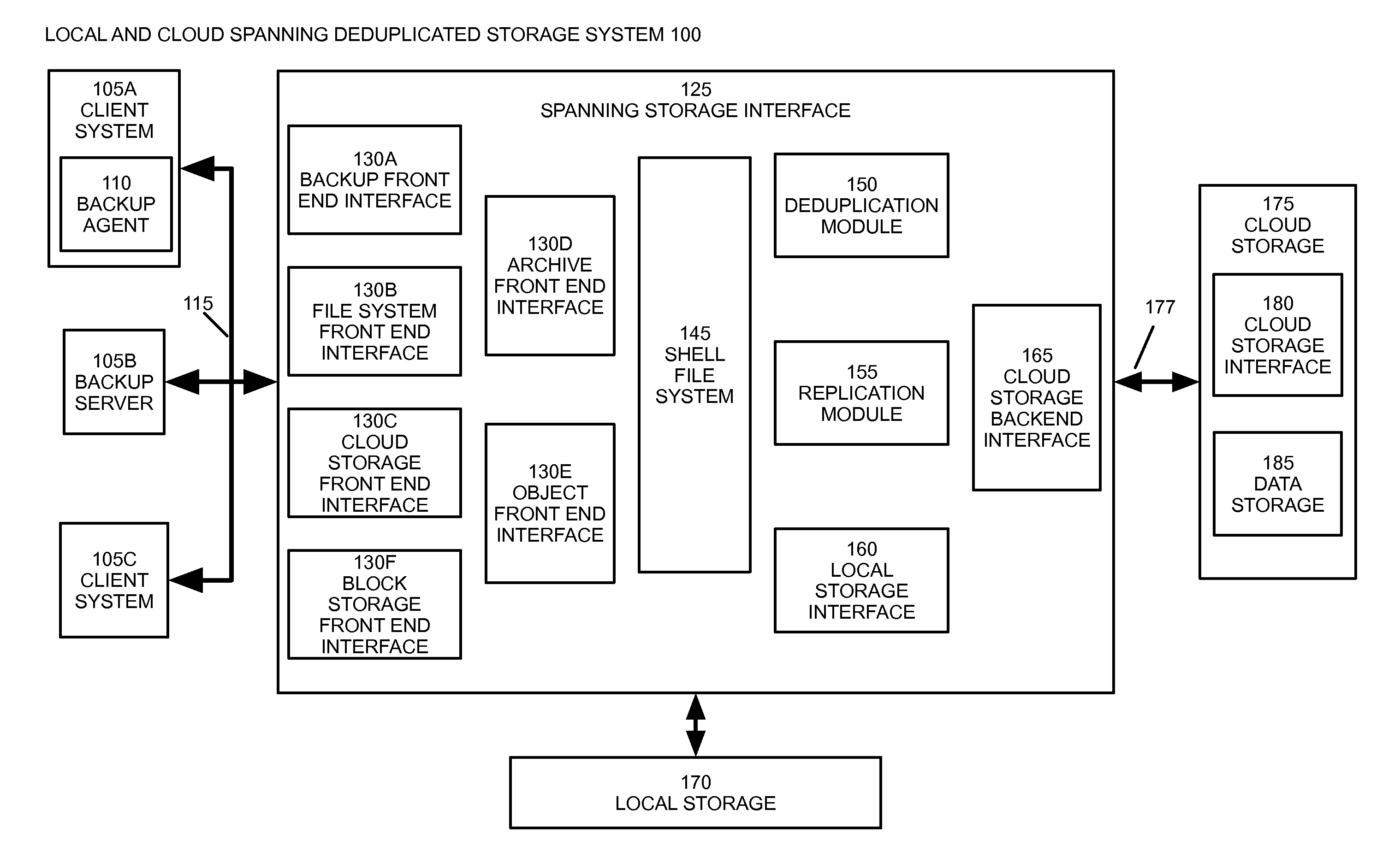
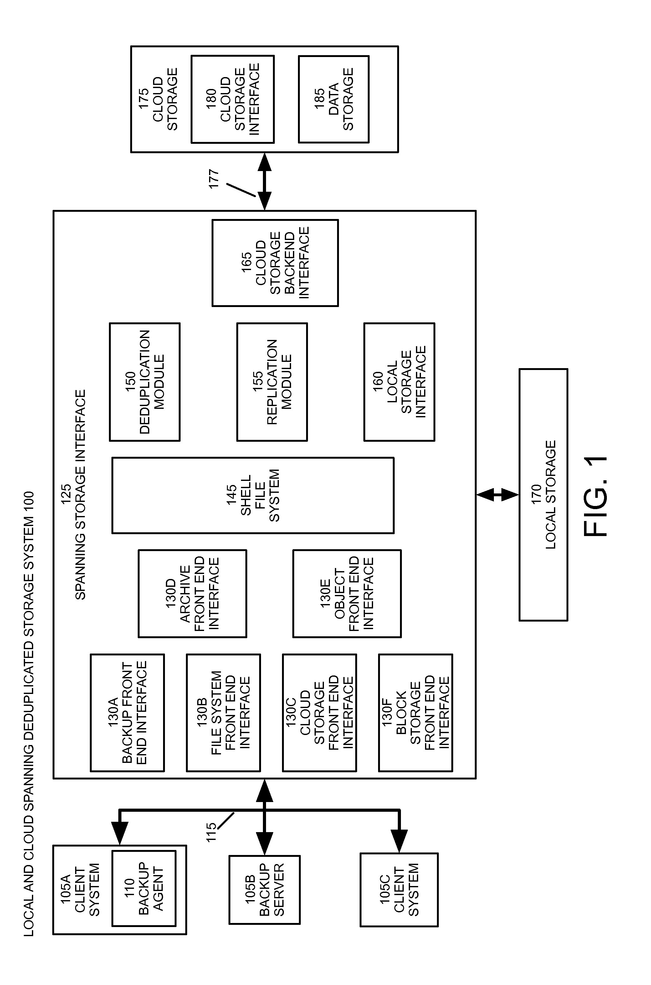
FIG. 1 illustrates an example of spanning storage interface 100 according to an embodiment of the invention. An example installation of the spanning storage interface 100 includes one or more client systems 105, which may include client computers, server computers, and standalone network devices. Client systems 105 are connected with a spanning storage interface 125 via a local-area network and / or a storage area network 115. Cloud storage 175 is connected with the spanning storage interface 125 by at least a wide-area network 177 and optionally an additional local area network. Cloud storage 175 includes a cloud storage interface 180 for communicating with the spanning storage interface 125 via wide-area network 177 and at least one physical data storage device 185 for storing data.

Embodiments of spanning storage interface 100 may support a variety of different storage applications using cloud data storage, including general data storage, data backup, disaster recovery, and deduplic...


PUM


Abstract

A spanning storage interface facilitates the use of cloud storage services by storage clients and may perform data deduplication. The spanning storage interface may include local storage for caching data from storage clients. A disaster recovery application includes at least first and second spanning storage interfaces at first and second network locations. The second spanning storage interface is provided for at least disaster recovery operations. The second spanning storage interface includes second local storage for improving data access performance. A copy of the local cache of the first spanning storage interface is transferred to the second local storage while the first network location is operating. In the event of a disaster affecting the first network location, the second spanning storage interface can provide data access to the first network location's data with improved performance from using the copy of local cache in the second local storage.

Description

BACKGROUND OF THE INVENTIONThe present invention relates generally to data storage systems, and systems and methods to improve storage efficiency, compactness, performance, reliability, and compatibility. In general, data storage systems receive and store all or portions of arbitrary sets or stream of data. Data storage systems also retrieve all or portions of arbitrary sets or streams of data. A data storage system provides data storage and retrieval to one or more storage clients, such as user and server computers. Stored data may be referenced by unique identifiers and / or addresses or indices. In some implementations, the data storage system uses a file system to organize data sets into files. Files may be identified and accessed by a file system path, which may include a file name and one or more hierarchical file system directories.Many data storage systems are tasked with handling enormous amounts of data. Additionally, data storage systems often provide data access to large n...

Claims


Application Information

Patent Timeline
IPC IPC(8): G06F11/20
CPCG06F17/30156G06F11/1453G06F11/2097G06F11/2094G06F11/1464G06F11/1451G06F16/1748G06F11/1458G06F11/1469
Inventor TALECK, GREGKESWANI, VIVASVATPARAB, NITINMACE, JAMES
Owner RIVERBED TECH INC
Why Eureka
Try Eureka