Mixing device in an exhaust gas pipe

a technology of mixing device and exhaust gas pipe, which is applied in the direction of machine/engine, separation process, transportation and packaging, etc., can solve the problems of engine efficiency decline, urea can crystallize, and the section of the exhaust pipe is progressively reduced, so as to improve the mixing efficiency and improve the fluid mixing effect. , the effect of efficient mixing

Active Publication Date: 2011-07-07
VOLVO LASTVAGNAR AB
View PDF9 Cites 98 Cited by
  • Summary
  • Abstract
  • Description
  • Claims
  • Application Information

AI Technical Summary

Benefits of technology

[0010]Thus, the invention provides a mixing device making it possible to obtain an asymmetrical velocity profile downstream from said device (as seen in the pipe median plane containing the nozzle axis). As a consequence, opposite the injection inlet, the first fluid flows quickly and drags the second fluid, making it deviate downstream with respect to its injection direction, thereby preventing said second fluid from hitting the pipe and making a deposit on it.
[0011]This result is obtained without impairing the mixing efficiency, since (i) the mixing device is designed to generate turbulence, thereby contributing to a better mixing of the fluids and (ii) the first fluid velocity downstream from said mixing device is not uniformly high, which would not provide enough time for both fluids to efficiently mix before they reach the pipe outlet.
[0012]It has to be noted that the mixing device is located close to the injection inlet, so that the velocity profile is substantially not altered when the first and second fluids meet.

Problems solved by technology

A problem with this type of exhaust gas treatment is that, before it has transformed into ammonia, urea can crystallize.
The consequence is that the cross section of the exhaust pipe is progressively reduced, which makes the engine efficiency decrease and which can seriously impair the engine operation in the long term.
This result is obtained without impairing the mixing efficiency, since (i) the mixing device is designed to generate turbulence, thereby contributing to a better mixing of the fluids and (ii) the first fluid velocity downstream from said mixing device is not uniformly high, which would not provide enough time for both fluids to efficiently mix before they reach the pipe outlet.

Method used


Image

  • Mixing device in an exhaust gas pipe
  • Mixing device in an exhaust gas pipe
  • Mixing device in an exhaust gas pipe

Examples


first embodiment

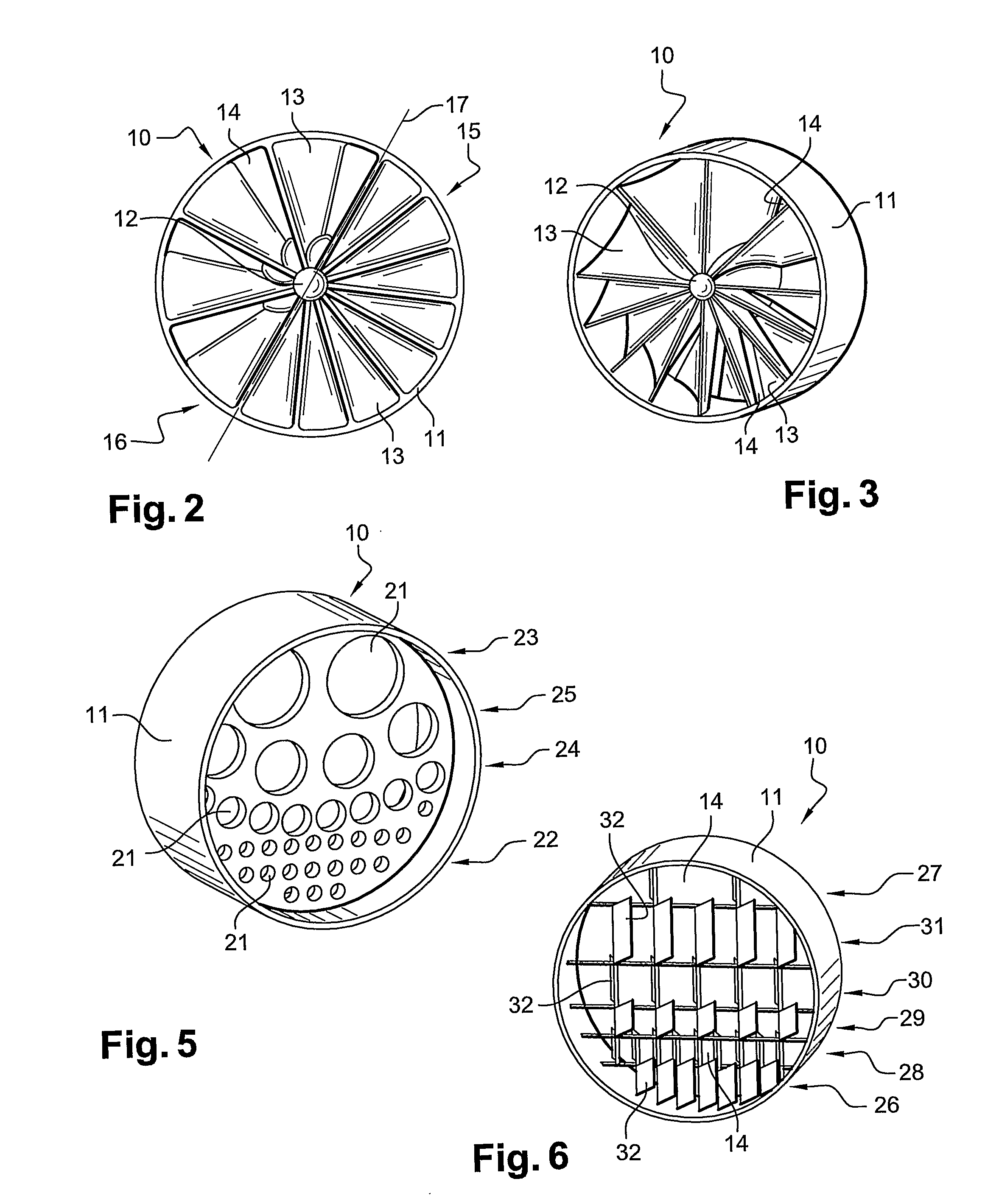
[0040]mixing device 10 is now described with reference to FIGS. 2 and 3.

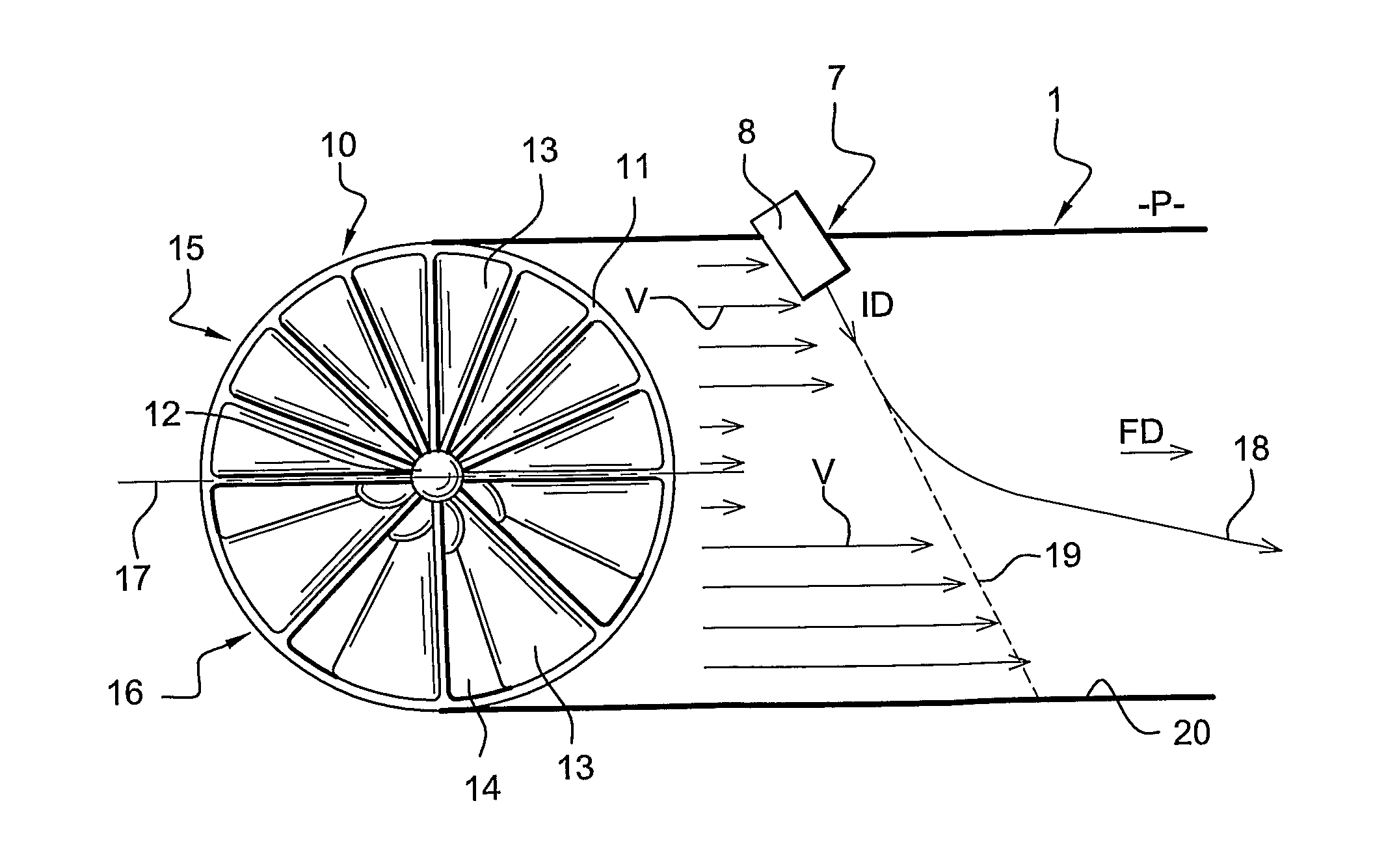
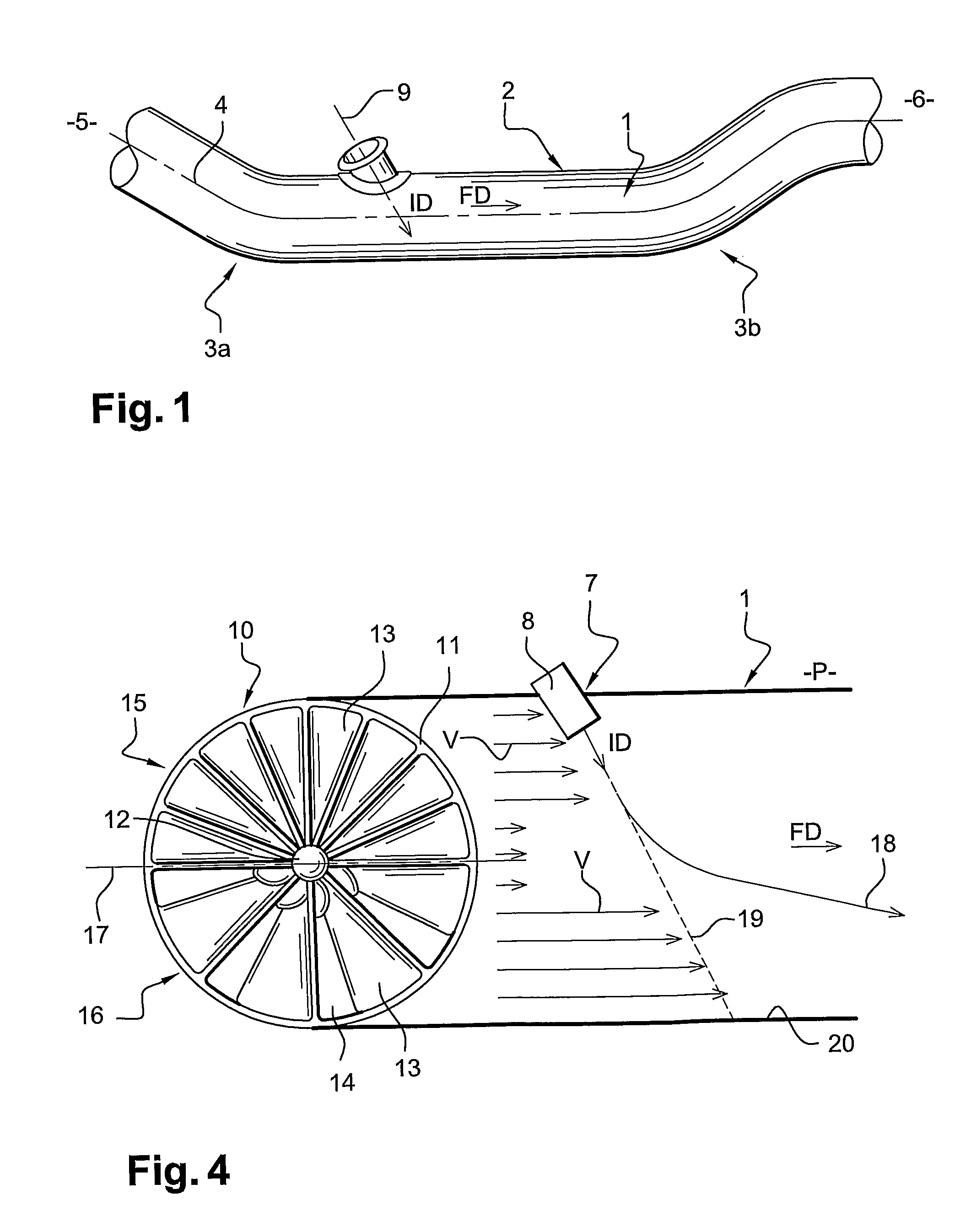
[0041]Said mixing device 10 comprises a central axis 12 substantially identical to the pipe axis 4 and a plurality of helical blades 13 extending radially from said central axis 12. Each helical blade is a flow diverting member which affects the flow of the first fluid. Passageways 14 are formed between two successive blades 13. It has to be noted that helical blades 13 are fixed, and do not rotate with respect to pipe axis 4.

[0042]Mixing device 10 has a first and a second portions 15, 16 inside sleeve 11, which are shaped as half discs and are located on both sides of the diameter plane 17 of mixing device 10 which is orthogonal to the pipe median plane P. First portion 15 is located on the side of nozzle 8, whereas second portion 16 is located opposite nozzle 8.

[0043]In each of first and a second portions 15, 16, the blades 13 are substantially regularly arranged. However, in second portion 16, the spacing bet...


PUM

PropertyMeasurementUnit
velocityaaaaaaaaaa
diameteraaaaaaaaaa
sizeaaaaaaaaaa

Abstract

In an exhaust gas pipe, a first fluid flows in a flow direction in the pipe, and a second fluid is injected inside the pipe by a nozzle, from an injection inlet arranged in the pipe wall, according to an injection direction. A mixing device fastened inside the pipe upstream from the injection inlet creates turbulence that helps the mixing of the fluids. The mixing device has a first portion located on the injection inlet side of the pipe and a second portion located opposite the injection inlet side of the pipe, the portions being designed so that the fluid velocity is higher downstream from the mixing device second portion than downstream from the mixing device first portion. An aqueous solution of urea can be injected inside an exhaust pipe of a diesel engine.

Description

BACKGROUND AND SUMMARY[0001]The present invention relates to a mixing device, especially designed to improve the mixing of two fluids such as exhaust gases from a diesel engine and an aqueous solution of urea.[0002]Exhaust gas formed in the combustion of fuel in an internal combustion engine contains a proportion of undesirable substances such as nitrogen oxides (NOx), carbon monoxide (CO), un-burnt hydrocarbons (HC), soot, etc. . . .[0003]To reduce air pollution, vehicles are therefore equipped with various systems that deal with undesirable substances in exhaust gas.[0004]A common exhaust gas treatment is a so called selective catalytic reduction (SCR). Exhaust gas wherein ammonia is added as a reducer is treated in a specific catalytic converter where nitrogen oxides are converted into water and nitrogen which are both non toxic substances. Ammonia is introduced in the form of urea in an aqueous solution from which ammonia is obtained through hydrolysis. Urea is usually nebulised...

Claims


Application Information

Patent Timeline
Patent Type & Authority Applications(United States)
IPC IPC(8): F01N3/10F01N3/00
CPCB01D53/90F01N3/10B01D2257/404B01D2258/012B01F3/04049B01F5/0473B01F5/0618B01F5/0682B01F5/0688B01F2005/0626B01F2005/0639F01N3/2066F01N3/2892F01N2240/20F01N2570/14F01N2610/02F01N2610/1453Y02T10/24B01D2251/2067Y02T10/12B01F23/2132B01F25/3141B01F25/43162B01F25/4316B01F25/431974B01F25/45B01F25/4521
Inventor VANVOLSEM, MICHELAMPERE, JULIEN
Owner VOLVO LASTVAGNAR AB
Why Eureka
Try Eureka