Casting level measurement in a mold by means of a fiber optic measuring method

a fiber optic measuring method and level measurement technology, applied in the direction of manufacturing tools, instruments, machines/engines, etc., can solve the problems of increasing radiation protection laws, requiring expensive sources of radioactive materials, and affecting the simple maintenance work

Inactive Publication Date: 2011-07-14
SMS DEMAG AG
View PDF3 Cites 18 Cited by
  • Summary
  • Abstract
  • Description
  • Claims
  • Application Information

AI Technical Summary

Benefits of technology

[0021]In a preferred embodiment, the sensor has an essentially rectangular solid shape, so that it can be installed in a groove on the side of the mold copper plate that faces away from the molten metal.
[0022]In another preferred embodiment, several parallel grooves are provided in the part of the sensor that contacts the copper plate in the direction of the liquid level. The parallel grooves run perpendicularly to the liquid level, and one or more optical fibers are arranged in each groove.
[0023]In another preferred embodiment, at least one optical fiber is arranged in each groove, and the optical fibers are arranged i...

Problems solved by technology

Method of this type have the disadvantage that they must meet ever more stringent radiation protection laws.
The use of radioactive materials hinders simple maintenance work and requires expensive sources of these materials.
Moreover, these methods are not suitable for determining the form of a meniscus wave, from which useful information can be obtained about other casting parameters, for example, the casting rate.
These methods have the disadvantage that in practice the thermocouples cannot be arranged at very narrow intervals.
Moreover, each individual test point requires a separate thermocouple, which leads to considerable material expense and above all a great deal of wiring work.
Finally, the thermocouples are also susceptible to the magnetic fields of an electromagnetic brake or electromagnetic ...

Method used


Image

  • Casting level measurement in a mold by means of a fiber optic measuring method
  • Casting level measurement in a mold by means of a fiber optic measuring method
  • Casting level measurement in a mold by means of a fiber optic measuring method

Examples


Embodiment Construction

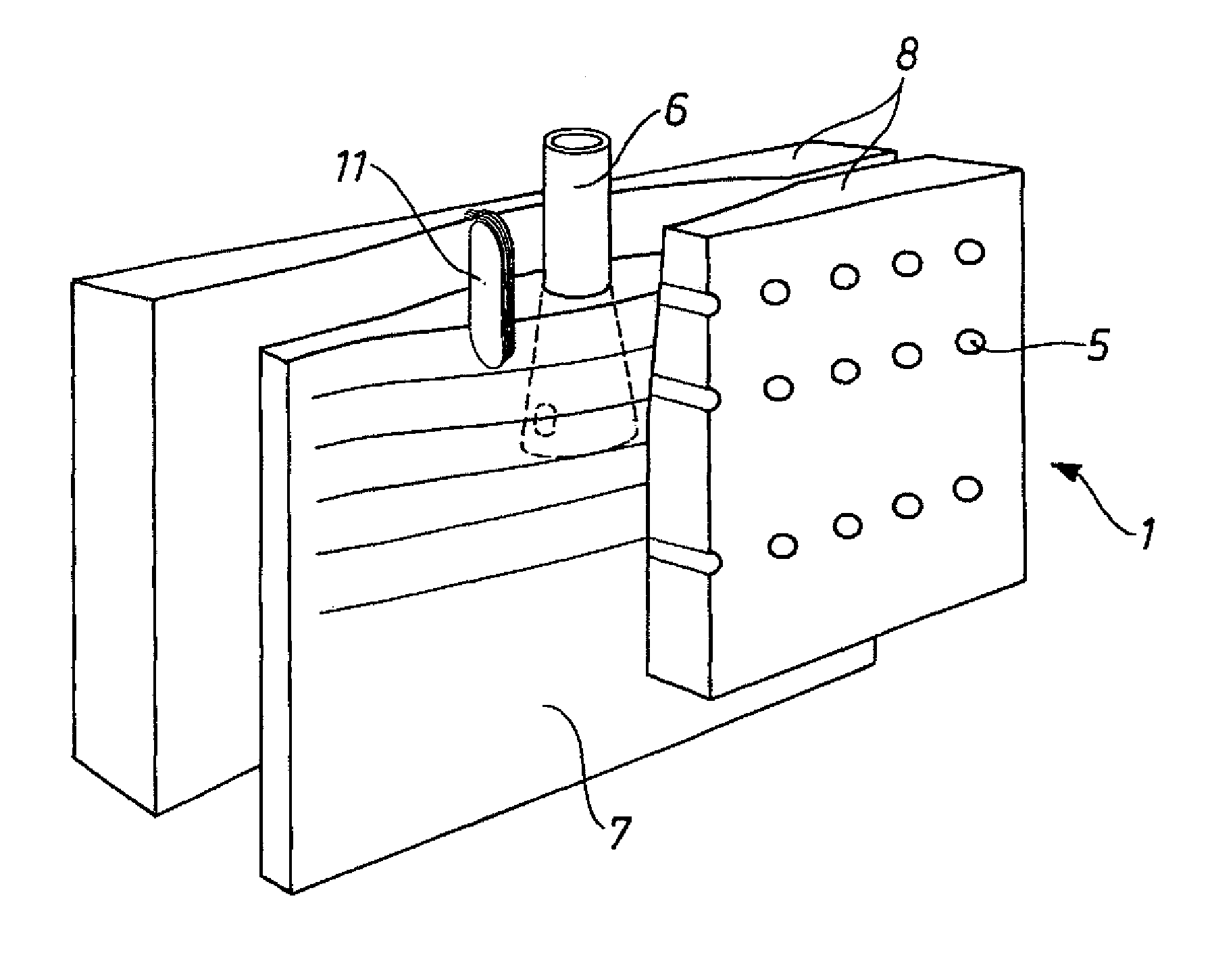
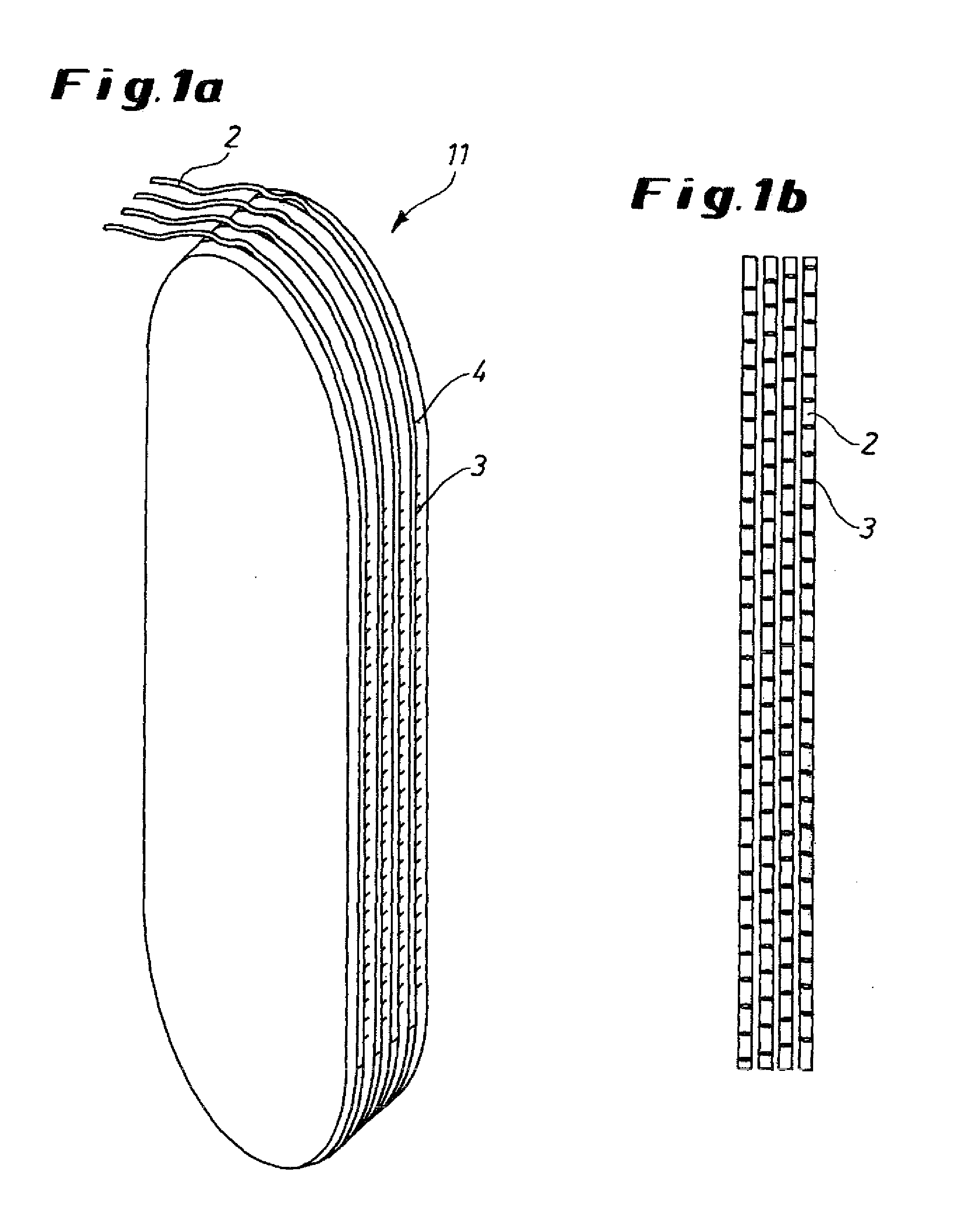
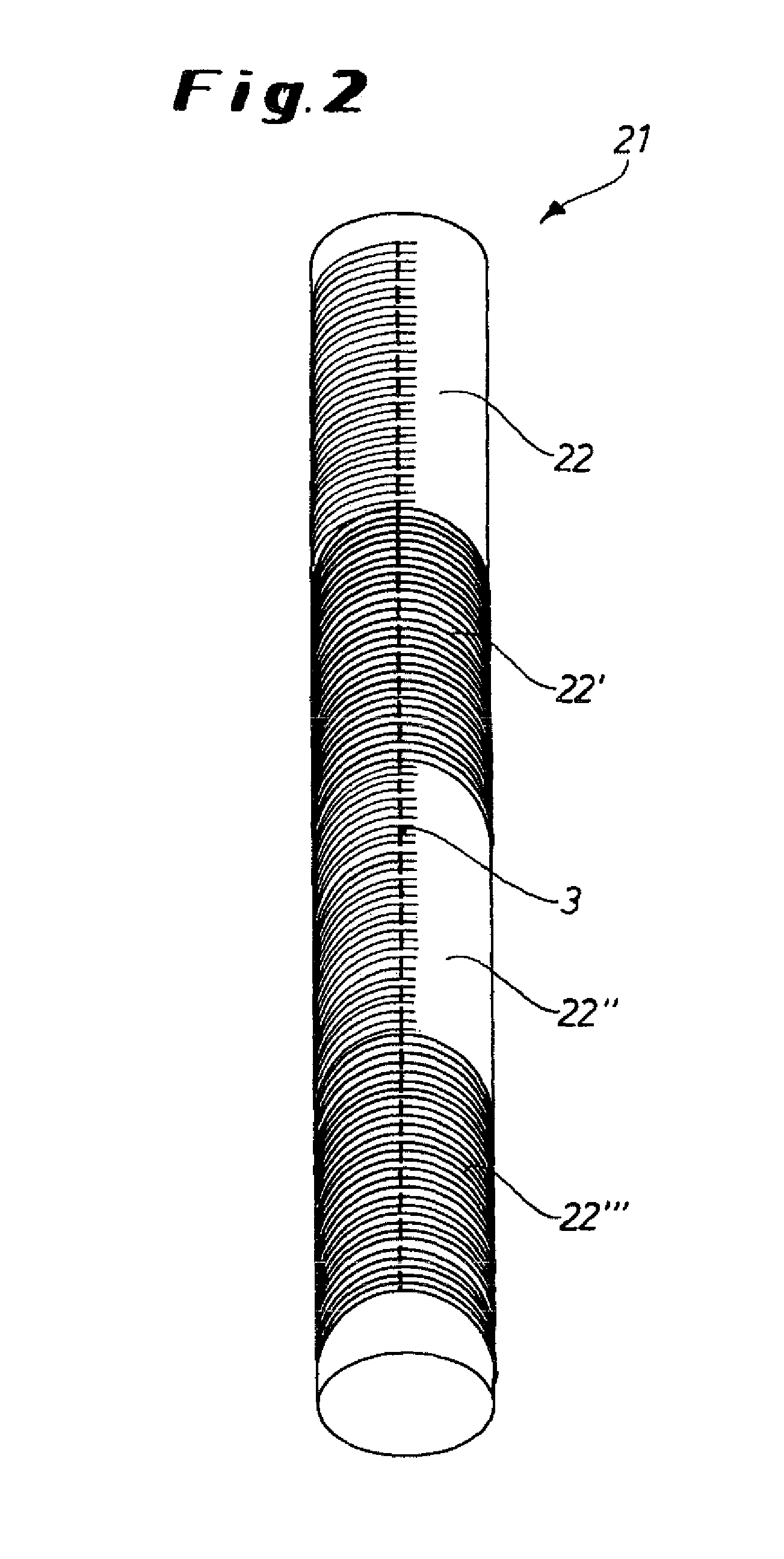
[0046]FIG. 1a shows a specific embodiment of a sensor 11 of the invention. The sensor 11 is shaped basically like a rectangular solid that is rounded at the upper and lower ends. The sensor 11 has four grooves 4, each of which contains an optical waveguide (optical fiber) or a fiber optic sensor 2. The drawing also shows test points 3 at which the temperature can be determined. The sensor 11 can be installed, for example, in a groove in the side of a mold copper plate that faces away from the molten metal, so that the optical fibers 2 are oriented in the direction of the molten metal. The sensor 11 is installed in such a way that the optical fibers 2 are in direct contact with the copper plate and are arranged between the water-cooling system of the copper plate and the molten metal in the direction of the molten metal. The sensor 11 illustrated in the drawing can have other geometries as well, as long as it is suited for installation in a groove of a mold copper plate. The sensor o...


PUM

PropertyMeasurementUnit
Temperatureaaaaaaaaaa
Shapeaaaaaaaaaa
Heightaaaaaaaaaa

Abstract

The invention provides a method for the cast level measurement in a mold by means of sensors for fiber optic temperature detection, which are disposed in the mold copper plate at the height of the casting level. The invention further comprises respective sensors. Fiber optic cables are disposed in said sensors, which allow simple, reliable and highly locally resolved temperature monitoring at the height of the casting level by means of a suitable temperature analysis system. By means of the temperatures determined by the sensors, a conclusion can be made as to the exact height of the casting level. Furthermore, the shape of the casting level shaft may be determined by means of which further parameters of the casting process become accessible.

Description

TECHNICAL FIELD[0001]The invention concerns a method for measuring the liquid level in a mold by one or more measuring fibers and / or sensors for fiber optic temperature measurement arranged in the mold copper plate at the level of the molten metal. The exact level of the molten metal can be derived from the temperatures determined by the fiber optic temperature sensors. The invention also includes the sensors used in this measuring method.PRIOR ART[0002]A well-known standard method for determining the level of the molten metal uses radioactive particles introduced into the mold. In this method, the emitted radiation is measured at various heights in the mold, which makes it possible to determine the level of the molten metal. To improve the measurement, a greater density of such particles can be introduced into the mold.[0003]Method of this type have the disadvantage that they must meet ever more stringent radiation protection laws. The use of radioactive materials hinders simple ma...

Claims


Application Information

Patent Timeline
IPC IPC(8): G01F23/22
CPCB22D2/003B22D11/182G01F23/292G01F23/246G01F23/248B22D11/202B22D2/00B22D11/20G01F23/22
Inventor ARZBERGER, MATTHIASLIEFTUCHT, DIRKPLOCIENNIK, UWE
Owner SMS DEMAG AG
Why Eureka
Try Eureka