Vacuum measuring device with interchangeable sensors

a technology of vacuum measuring device and sensor, which is applied in the direction of instruments, electric digital data processing, computer peripheral equipment, etc., can solve the problems of accidental wrong connection, inability to operate, and damage to the vacuum sensor or the vacuum measuring device, so as to simplify the task

Inactive Publication Date: 2011-07-14
PLOECHINGER PATENT
View PDF2 Cites 12 Cited by
  • Summary
  • Abstract
  • Description
  • Claims
  • Application Information

AI Technical Summary

Benefits of technology

[0012]When a vacuum measuring device is attached to a vacuum sensor having an identification disk, a microcontroller within the vacuum measuring device becomes operatively connected to the identifiable electric or electronic component in the identification disk. The microcontroller identifies the identifiable electric or electronic component, e.g. by determining the resistance value of an identifiable resistor or reading an identification number out of an identifiable electronic memory. The identification of a particular vacuum sensor may be used to associate vacuum pressure measurements with a particular vacuum sensor, and thus a particular vacuum container. The microcontroller in the measuring device may comprise an electronic memory and store vacuum measurement valu

Problems solved by technology

It also creates a risk of accidentally connecting the wrong vacuum measuring device to a vacuum sensor, which may lead to incorrect measurements, or may even cause damage to the vacuum sensor or the vacuum measuring device.
Those measuring devices however require an operator to identify the sensor model to be connected and select the correct socket for the sensor, still leaving the opportunity

Method used


Image

  • Vacuum measuring device with interchangeable sensors
  • Vacuum measuring device with interchangeable sensors
  • Vacuum measuring device with interchangeable sensors

Examples


Embodiment Construction

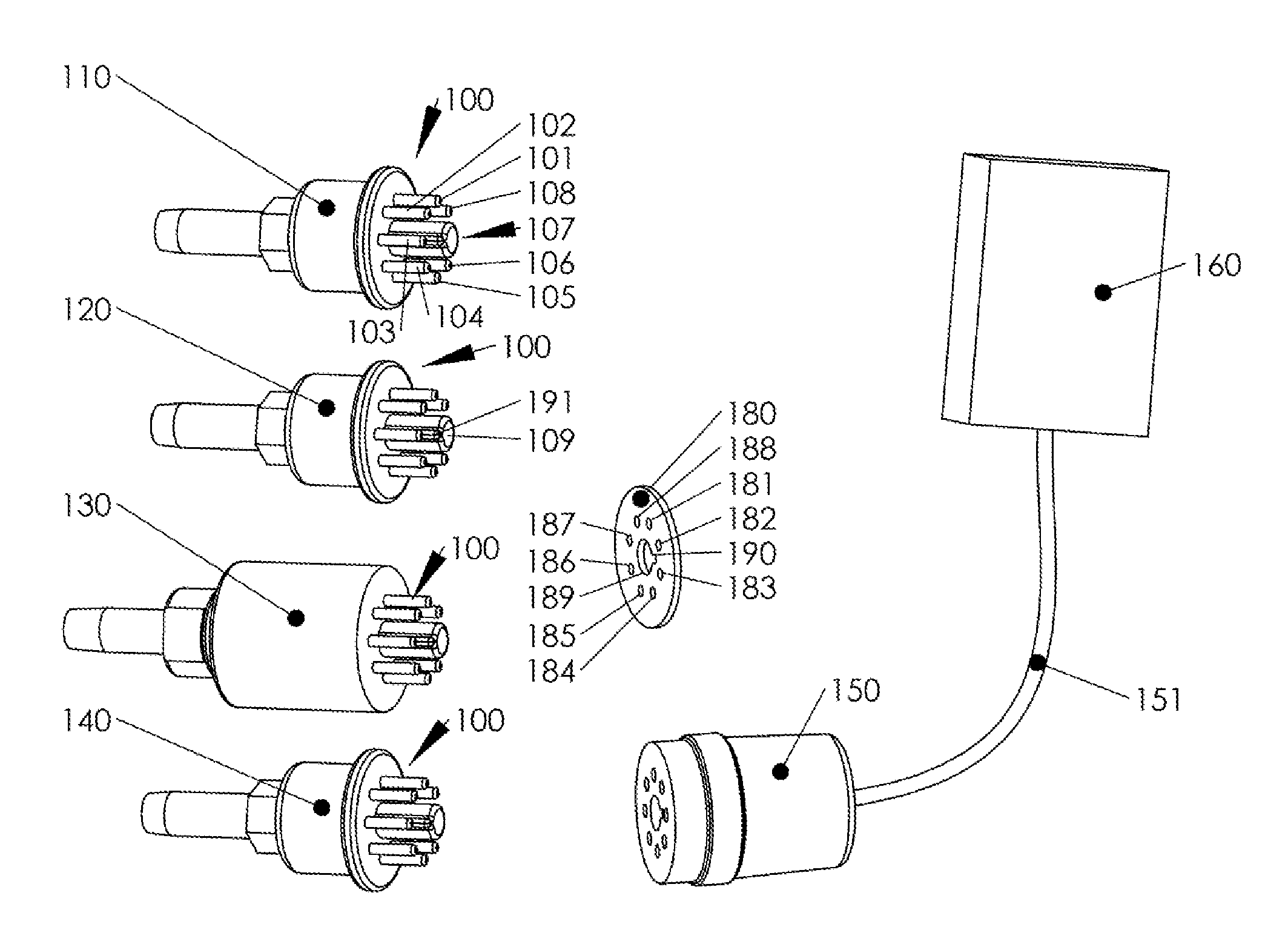
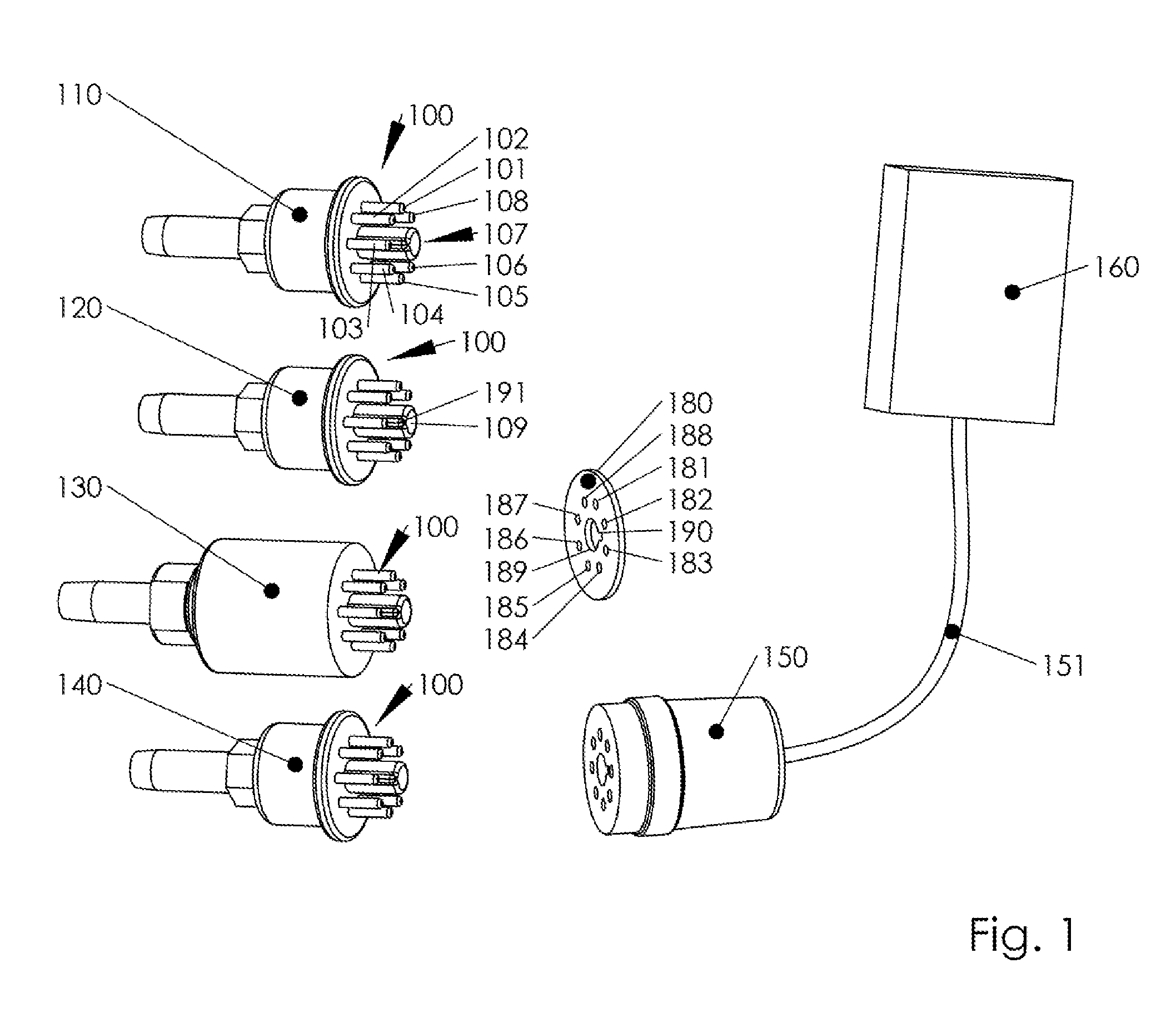
[0019]Referring to FIG. 1, an exemplary embodiment in which aspects of the present invention are advantageously practiced is illustrated generally. Several vacuum sensors (110, 120, 130, 140) are shown, which utilize a common connector layout. An identification disk 180 is provided, which can be placed between the male connector 100 of vacuum sensor 110, 120, 130 or 140 and socket 150 of a vacuum measuring device 160. Socket 150 is connected to a pig-tail 151, which is terminated in vacuum measuring device 160. Vacuum measuring device 160 is operatively connected to one of the vacuum sensors 110, 120, 130 or 140 trough connector 100, when plugged into socket 150. Vacuum measuring device 160 may comprise a display for displaying the vacuum pressure. Vacuum measuring device 160 may also comprises an output (not shown), which is configured to provide a vacuum pressure signal. The output may be any form of communicable electrical signal, e.g. a variable voltage, variable current, pulse ...


PUM


Abstract

An interoperable vacuum measuring device is presented, which automatically adjusts to one of two or more vacuum sensors having different electrical characteristics. The interoperable vacuum measuring device in a first step detects which type of vacuum sensor it is connected to. In a second step it controls and evaluates the vacuum sensor, using control parameters determined in response to the detection of the first step.
Detection of a vacuum sensor type is achieved by measuring the electrical resistance between any two pins of a vacuum sensor's connector and comparing the measured resistance values with stored resistance values of known vacuum sensors.
Further, a vacuum measuring device is presented, which automatically identifies a vacuum sensor, and associates a vacuum pressure measurement with a vacuum sensor. The identification of a vacuum sensor is facilitated by an identification disk, which is placed onto and operatively connected to the male terminals of a vacuum sensor's connector.

Description

CLAIM FOR PRIORITY[0001]This application claims priority of U.S. provisional patent application No. 61 / 294,510, filed Jan. 13, 2010, which is hereby incorporated by reference.TECHNICAL FIELD[0002]The present invention generally relates to vacuum measuring devices, and more particularly, to vacuum measuring devices with interchangeable vacuum sensors.BACKGROUND OF THE INVENTION[0003]Vacuum measuring systems are widely used and typically comprise a vacuum sensor and a vacuum measuring device. The vacuum measuring device controls and reads the vacuum sensor. The vacuum sensor is typically permanently attached to a vacuum container using an air-sealed interface. The vacuum measuring device may be portable and carried between several vacuum containers, especially if continuous monitoring of the vacuum container is not required. The vacuum sensor is typically connected to the vacuum measuring device using a plug-in connector. Commonly used vacuum sensors are thermocouple gauge tubes.[0004...

Claims


Application Information

Patent Timeline
IPC IPC(8): G01L9/00G06K19/077G06K19/00G06K7/01
CPCG01L19/0007G01L27/00G01L21/14
Inventor PLOCHINGER, HEINZSICKINGER, GEORG
Owner PLOECHINGER PATENT
Why Eureka
Try Eureka