Micro- and nano-structured LED and OLED devices

Inactive Publication Date: 2011-07-14
RGT UNIV OF CALIFORNIA
View PDF1 Cites 22 Cited by
  • Summary
  • Abstract
  • Description
  • Claims
  • Application Information

AI Technical Summary

Benefits of technology

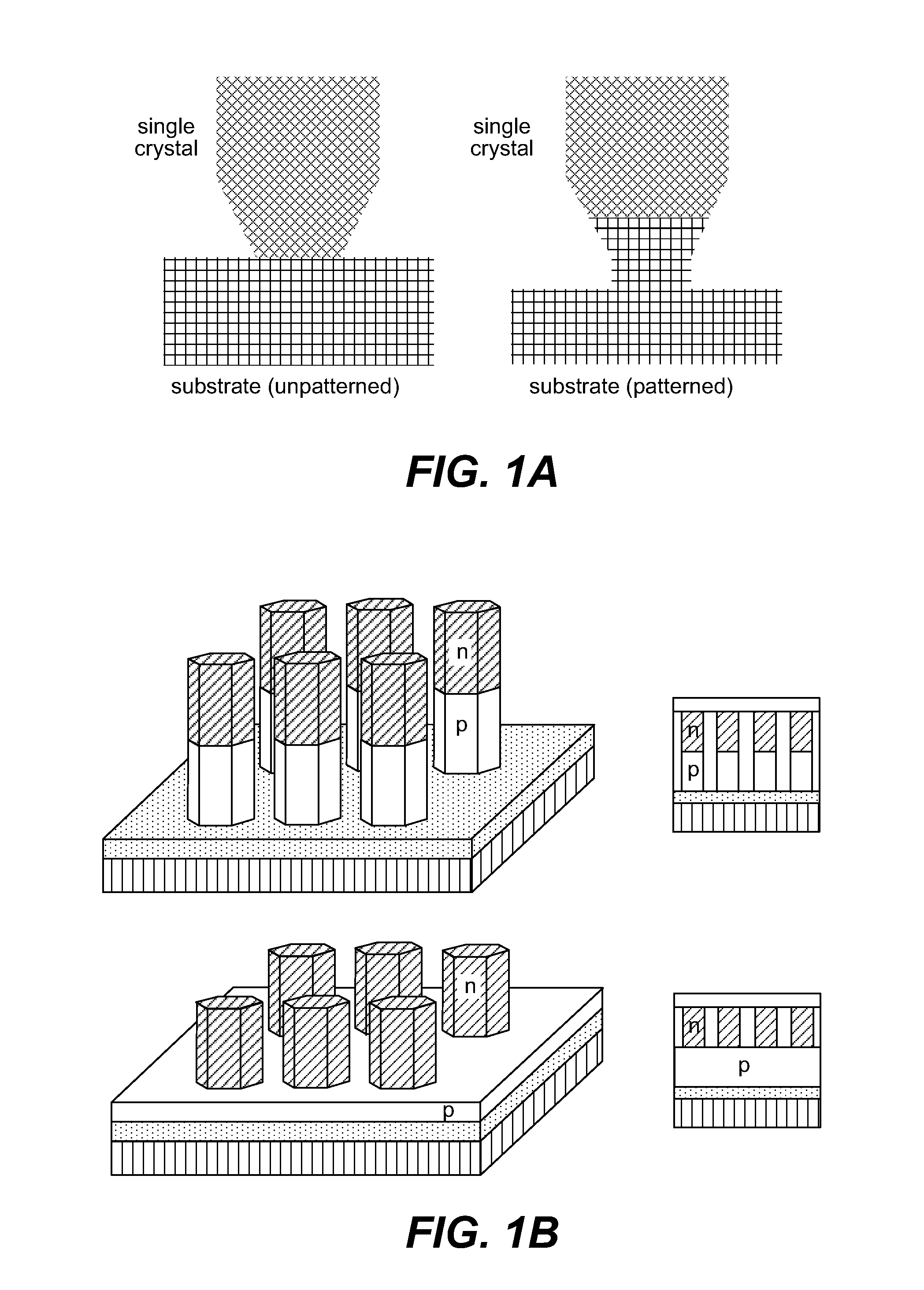
[0009]The present invention provides structured LED and OLED devices and component structures with improved efficiency and reduced defects. The improved performance of these devices is enabled by the use of micro- or nano-structured features that reduce lattice strain and improve p-doping in inorganic LEDs, and facilitate carrier injection and recombination of OLEDs. The structures can also confine current flow and provide internal light guiding to enhance efficiency and thereby improve device performance.

Problems solved by technology

Due to the nonexistence of lattice-matching substrates it is extremely difficult to reduce this type of defect concentration in wide band-gap semiconductor films.
Device testing indicates that the current efficiency increases with the inclusion of the porous oxide layer, which has a low effective refractive index due to the high porosity, together with a deep valence band to block holes for the hole-dominant device.
However, the efficiency reduces when the thickness of the layer becomes too thick due to insufficient hole injection. FIG. 8 shows current efficiency measurements of four devices with different thickness of porous TiO2 layer between ITO and organics.

Method used


Image

  • Micro- and nano-structured LED and OLED devices
  • Micro- and nano-structured LED and OLED devices
  • Micro- and nano-structured LED and OLED devices

Examples


Embodiment Construction

[0031]Reference will now be made in detail to specific embodiments of the invention. Examples of the specific embodiments are illustrated in the accompanying drawings. While the invention will be described in conjunction with these specific embodiments, it will be understood that it is not intended to limit the invention to such specific embodiments. On the contrary, it is intended to cover alternatives, modifications, and equivalents as may be included within the spirit and scope of the appended claims. In the following description, numerous specific details are set forth in order to provide a thorough understanding of the present invention. The present invention may be practiced without some or all of these specific details. In other instances, well known process operations have not been described in detail so as to not unnecessarily obscure the present invention.

INTRODUCTION

[0032]The present invention uses a nanostructured approach as an alternative to conventional unstructured m...


PUM


Abstract

Structured LED devices and component structures with improved efficiency and reduced defects are enabled by the use of micro- or nano-structured features that reduce lattice strain and improve p-doping in inorganic LEDs, and facilitate carrier injection and recombination of OLEDs. The nanostructures can also confine current flow and provide internal light guiding to enhance efficiency and thereby improve device performance.

Description

CROSS-REFERENCE TO RELATED APPLICATIONS[0001]This application claims priority to U.S. Provisional Patent Application No. 61 / 083,350, titled MICRO- AND NANO-STRUCTURED LED AND OLED DEVICES, filed Jul. 24, 2008, the disclosure of which is incorporated herein by reference in its entirety and for all purposes.STATEMENT OF GOVERNMENTAL SUPPORT[0002]The invention described and claimed herein was made at least in part utilizing funds supplied by the U.S. Department of Energy under Contract No. DE-AC02-05CH11231. The Government has certain rights in this invention.BACKGROUND OF THE INVENTION[0003]A light-emitting diode (LED) is a semiconductor diode that emits light when electrically biased in the forward direction of the p-n junction. The color of the emitted light depends on the composition and condition of the semiconducting material used, and can be infrared, visible, or ultraviolet. As in other diodes, an LED is a semiconducting structure consisting of p- and n-type semiconductor mater...

Claims


Application Information

Patent Timeline
IPC IPC(8): H01L33/06B82Y40/00B82Y99/00
CPCH01L33/18B82Y20/00
Inventor MAO, SAMUEL S.
Owner RGT UNIV OF CALIFORNIA
Why Eureka
Try Eureka